


Sensor Locator
As of August 5th, 2025, Golaem will no longer provide direct support.
All support for Autodesk Golaem will now be handled exclusively through Autodesk support channels and this website will be deactivated soon.
Please bookmark the Autodesk Golaem Support section for any future support needs related to Autodesk Golaem packages.
The Sensor Locator defines a custom perception volume that can be used by Crowd Entities to perceive obstacles or other entities in a simulation. The perception volume is defined by mapping one or more meshes to the Sensor Locator. A given entity detects an object (obstacle or entity) if that object (or more precisely, its Perception Shape defined in the Character Maker or overridden in the Entity Type) intersects the entity's perception volume. Each sensor will output the set of objects it detects and the distance to each of those objects.
Creation
- Golaem Shelf:

- Golaem Menu: Sensor Locator
- MEL Command: glmSensorLocatorCmd
Sensors are defined on a per scene basis and they can be enabled on an entity using the Activate Sensor Behavior.
Configuration
Sensor Attributes
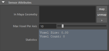
| In Maya Geometry |
Maya meshes that define the sensor geometry. Several meshes or a transform containing one or more meshes can be mapped. Each Maya mesh must be closed, convex and its face normals must point outwards or the perception volume might be incorrect. A warning message is displayed in most cases when the mesh does not respect these prerequisites. There might still be some cases where the Sensor Locator does not detect invalid meshes. To make sure that the input geometry is valid, display the voxels (see the Display Attributes) and make sure they fill the inside of each mesh.
The sensor overall shape doesn't need to be convex, as long as it's made up of multiple individual convex meshes. The geometry is considered X-front and Y-up. The (0, 0, 0) coordinate will be aligned to the position of the crowd entity. |
| Max Voxel Per Axis |
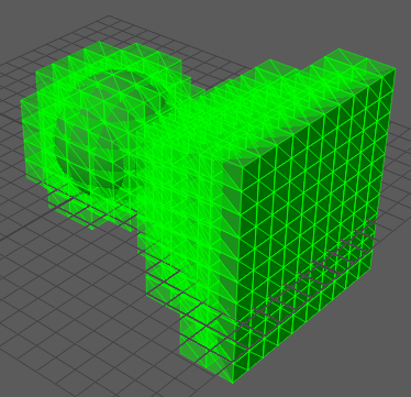
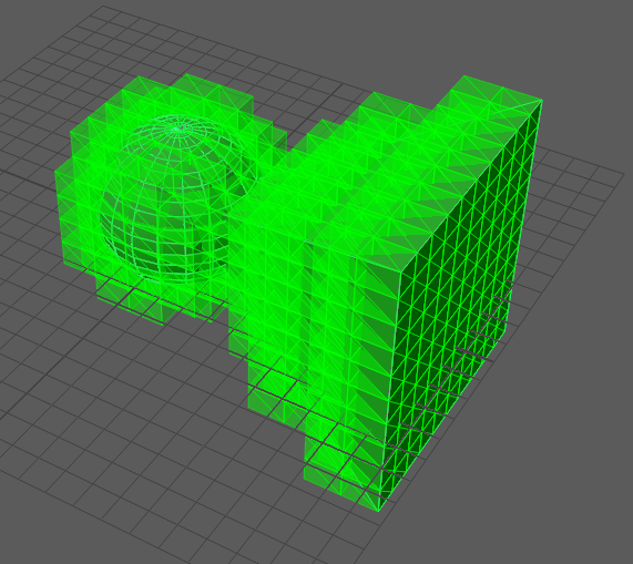
Max voxel count on the X, Y or Z axis. The Sensor Locator transforms the Maya geometry into a set of voxels, by taking its bounding box and dividing it into voxels. The size of each voxel on an axis is determined by dividing the size of the bounding box on that axis by the voxel count on that axis. A voxel is filled if its center lies inside the mesh shape. By increasing the voxel count, the input geometry is approximated more precisely at the expense of performance.
|
For performance reasons, the AABB tree structure is what is actually used to determine if an object is detected. Thus, for more precision, Max Voxel Count can be increased. Check the viewport display to visualize the voxels (see Dsiplay Attributes below).
Simulation Attributes
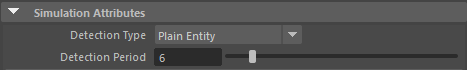
| Detection Type |
Defines the type of objects that are detected by the sensor. Two types are available:
|
| Detection Period | The detection period in number of frames. It defines the number of frames to wait before updating the detected objects. A value of 1 means the sensor is updated at each frame when active (using the Activate Sensor Behavior). Increasing this parameter will also increase performance at the expense of a less precise detection. |
Filters
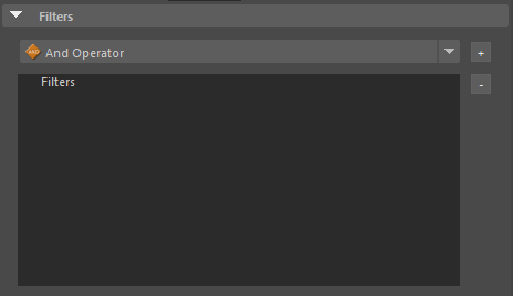
Filters allow to exclude detected objects based on different criteria.
To add a filter, select it from the drop-down list and click on the "+" button. It will be added to the list of filters below. Filters are organized in a tree view, as some of them (the filter operators) allow adding subfilters. To add a filter as a child of another one, select its parent in the filters tree view and click on the "+" button.
To remove a filter, select it in the filters tree view and click on the "-" button.
Some filters have parameters. The parameters can be viewed and changed by selecting the filter.
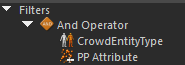
 AND Operator AND Operator |
This is a filter operator that accepts two filter operands. The sensor will detect objects that match both its child filters.
In the example above, the Sensor will detect entities that have a given Entity Type (CrowdEntityType filter) and at the same time have a given PP Attribute value (PP Attribute Filter) |
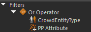
 OR Operator OR Operator |
This is a filter operator that accepts two filter operands. The sensor will detect objects that match any of its child filters.
In the example above, the Sensor will detect entities that have a given Entity Type (CrowdEntityType filter) or entities taht have a given PP Attribute value (PP Attribute Filter) |
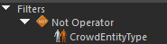
 NOT Operator NOT Operator |
This is a filter operator that accepts one filter operand. The sensor will detect objects that do match its child filter.
In the example above, the Sensor will detect entities that do not have a given Entity Type (CrowdEntityType filter) |
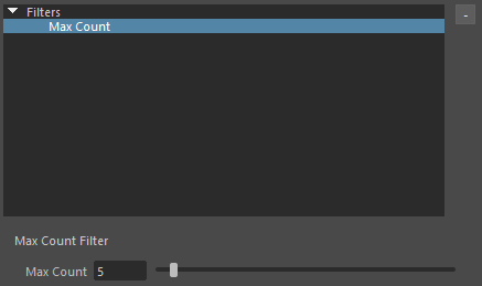
| Max Count |
Limits the number of detected objects to a given value.
Parameters
|
| Navmesh Visibility | This filter is valid only when a Navigation Mesh is used in the crowd simulation. The filter excludes objects that are not reachable on the navigation mesh and objects that are not on the same connex area as the current entity. For example, an entity located under a bridge won't detect entities above the bridge. |
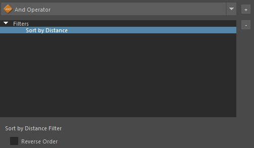
| Sort by Distance |
This is a special filter that does not exclude any object, but rearranges them based on their distance to the current entity.
Parameters
|
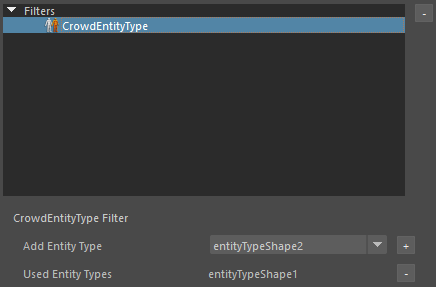
 CrowdEntityType CrowdEntityType |
This filter is only valid if the detection type is set to Plain Entity. It allows to keep only entities having a given Entity Type.
Parameters
|
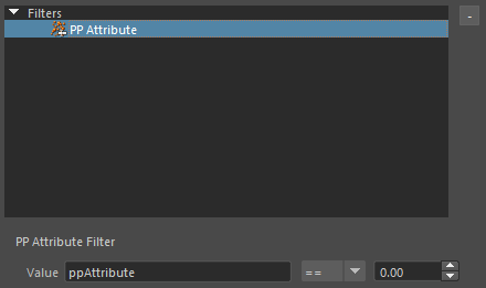
 PP Attribute PP Attribute |
This filter is only valid if the detection type is set to Plain Entity. It allows to keep only entities having a PP Attribute that satisfies an expression.
Parameters
|
| Golaem Attribute |
This filter is only valid if the detection type is set to Plain Entity. It allows to keep only entities having a Golaem Attribute that satisfies an expression. Parameters
|
| External Entity |
This filter is only valid if the detection type is set to Plain Entity. It allows to keep only External Entity Locators. |
Filter Stacking
Filters can be combined using filter operators (AND, OR and NOT) but they can also be stacked at top level (see example below). The order in which they are added and displayed in the filters tree view is important as it defines the order in which the filters get applied. Filters operate on a list of objects, so if some objects get excluded by a filter, the following filter will only operate on the remaining objects.
Let's say that we want to detect only the closest 3 entities of a given type, entityTypeShape1. To achieve this, we can use three filters, as shown below:
 |
 |
| Example A | Example B |
In example A, the sensor first keeps only entities of type entityTypeShape1 (CrowdEntityType Filter), then keeps only the first 3 entities in the remaining list (Max Count Filter), and finally sorts the entities by distance (Sort by Distance Filter). In example B, the Max Count and Sort By Distance filters are switched, so the sensor first keeps only entities of type entityTypeShape1 (CrowdEntityType Filter), then sorts the resulting entities by distance (Sort by Distance Filter), and finally it keeps only the first 3 entities in the remaining list (Max Count Filter). As the initial list of detected objects depends on the shape of the sensor and is not ordered in any way, the two examples will produce different results. Only example B really works the way it is intended, and detects the closest 3 entities of type entityTypeShape1. Example A detects 3 entities of type entityTypeShape1 that are output in a list ordered by distance, but they are not necessarily the 3 closest entities of that entity type, as the Max Count Filter gets applied after the Sort by Distance filter.
Another way to obtain the same result would have been to create the filters in this order: Sort by Distance, CrowdEntityType, Max Count. However, this means that the Sort by Distance filter would be applied to all the entities in the perception environment, and not just on the entities of type entityTypeShape1, thus being more CPU intensive.
Entity Alignment Attributes
These attributes define how the sensor aligns to the direction of the entity.
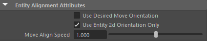
| Use Desired Move Orientation | When enabled, the sensor is aligned with the desired move orientation instead of the move orientation. |
| Use Entity 2d Orientation Only | When enabled, the sensor is aligned only with the heading orientation of the entity. |
| Move Align Speed | Speed at which the alignment is done with the move orientation instead of the body orientation. |
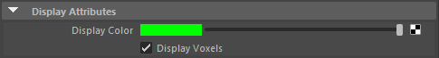
Display Attributes
These parameters define how the Sensor Locator is drawn in Maya's viewport. They are useful when first creating the sensor, but can be disabled afterwards.
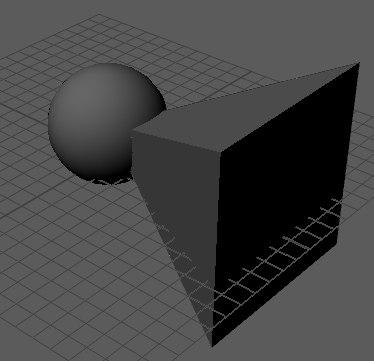
The examples in the table below were created using the Maya geometry in the image below.
| Display Color | Defines the color of the Sensor Locator in Maya's viewport. |
| Display Voxels |
When enabled, draws the sensor voxels in Maya's viewport.
|