


Stadium Placement
As of August 5th, 2025, Golaem will no longer provide direct support.
All support for Autodesk Golaem will now be handled exclusively through Autodesk support channels and this website will be deactivated soon.
Please bookmark the Autodesk Golaem Support section for any future support needs related to Autodesk Golaem packages.
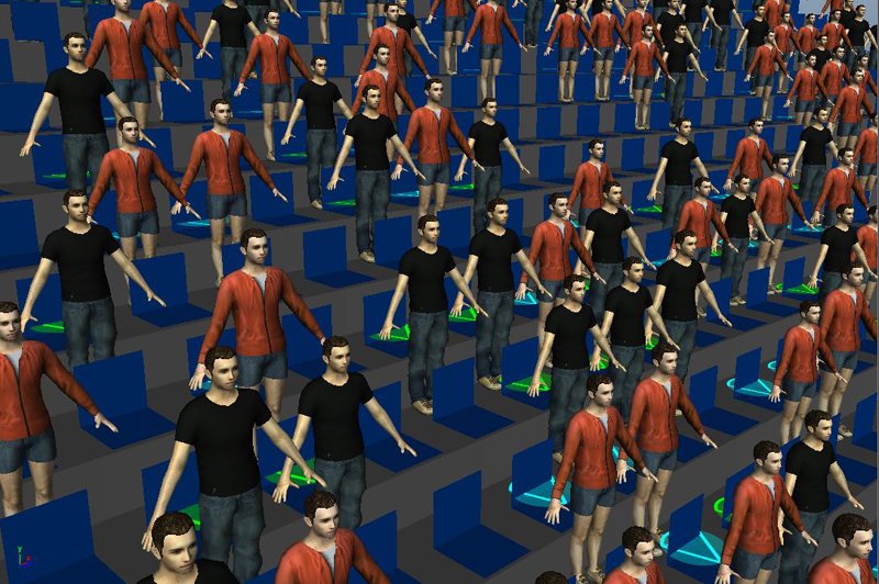
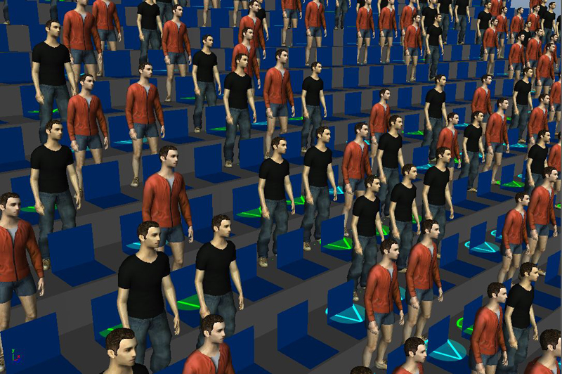
The basic workflow details how to quickly populate a stadium.
However, there are as many stadium setup as project, and the explained method may not be suitable for all projects. Today let's see some alternative methods for placement. The method to be chosen mainly depends on the input geometry, distance from the camera, behaviors to implement...
Face Componentsa
This is the method we already exposed.
![]()
Select faces in your geometry and choose the "Selected object or component" mode  in the Population Tool Creator Tool Panel. See here for more details.
Placement Using Seats Pivots
For stadiums which seats are individual meshes, you can select theses meshes and place people relatively to the mesh pivot.
Just select all these meshes in object mode (the default selection mode)
Then click on the Golaem Crowd Population Tool Creator  , and select the "Selected object or component" mode in the Tool Settings panel.
As usual, you can change the population tool parameters to populate only some of the seats, add a bit of noise...
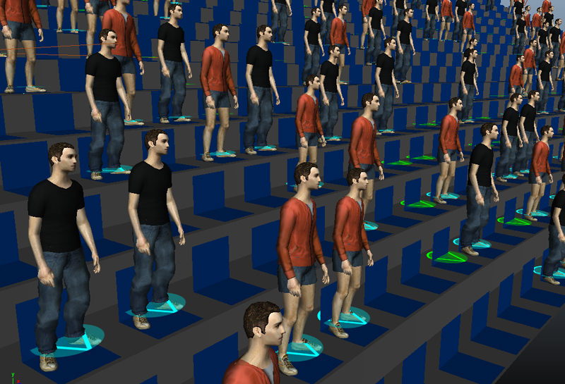
Usually the pivot of your seat object is centered on the seat, but it is not always what you want. For example if you generate standing supporters, they will be standing inside the seats, which depending on your camera angle can be a very big problem.
In those cases, do not forget that you can either change the pivot of your object before populating the stadium, or move the whole population tool using the usual Maya Translation tool. See an example below where we moved the population tool forward so that the characters are generated in front of the seats.
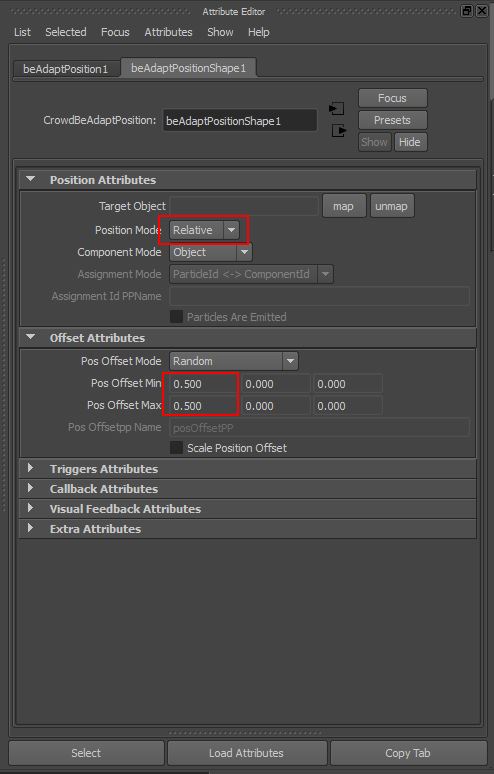
Offsetting the initial position based on Behavior
Assuming you have placed your entities based on polygons center and depending on your motions it may happen that you need to offset the characters before starting the motion. Indeed, when the simulation starts, a sit characters needs to have its root bone above the center of the seat, but a standing character needs to have it in front of the seat. Here is how to tweak their positions.
 , add a motion using a Motion Behavior. Your entities are now animated but still placed at the same position. In order to offset their positions, just add a Adapt Position Behavior
  before the Motion Behavior.
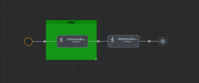
Using Navmesh For Complex Placement
When it is not possible to use the component or object mode, you can compute a navmesh  for your stands and place your characters using a regular population tool (most likely a point shape one
  if you want to be able to set a number of rows and columns). This placement mode also offers the advantage of being able to use noise without characters overlapping each others.
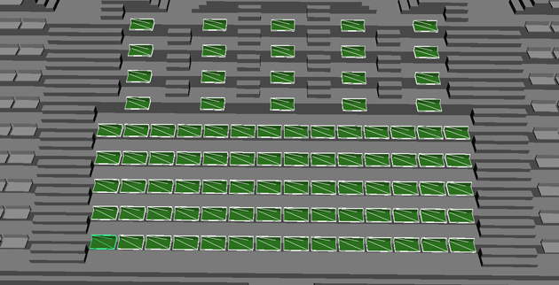
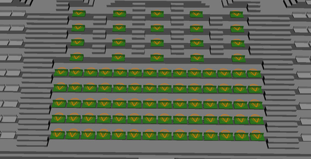
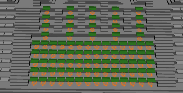
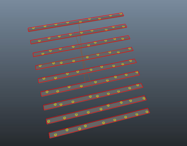
The first step is to select the stand mesh and to compute a navmesh (for this case I prefer to use the "Exact subdivision mode", you just need to uncheck the "Keep Only Greatest Connex Zone" in the Advanced Parameters tab).
Then you can place a point shape population tool and adjust its number of row/columns, move it and adjust the distance between characters, to match your stands. Do not forget to adjust the particle radius as well so that they can fit into the stands.
Notice that although we requested 12 columns, given the distance parameters, only 9 could be generated. The advantage of using a navmesh is that the extra particles are not generated outside the stand. They are not generated at all.
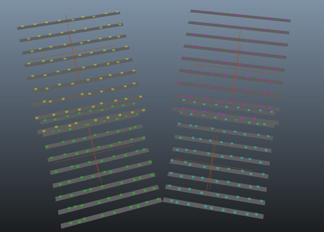
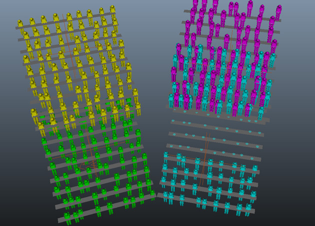
Placement With Multiple Terrains
For example when using the navmesh method to place your characters, it can be useful to create more than one terrain. In the example below, we created only one terrain with all stands and try to generate people on the top stand. Unfortunately, depending on the parameters used, some characters may get generated on other stands.
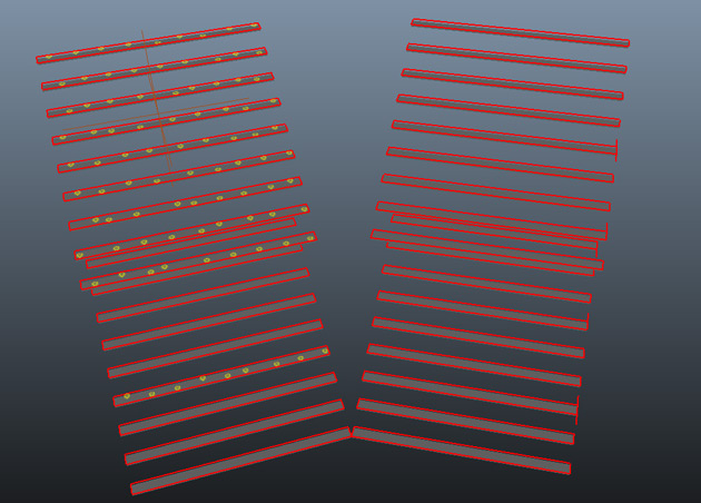
A clever solution for this case is to use a different terrain per particle tool.
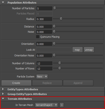
In the picture below, we included only the top-left stand in a terrain and generated particles on it. The terrain a population tool should use can be selected in the Terrain Attributes:
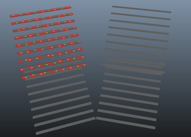
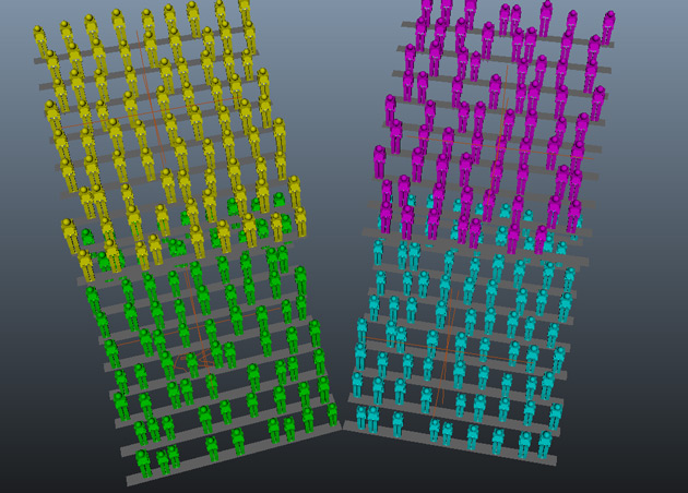
Here is the result when placing 4 particle tools, using one terrain per stand. A different Entity color has been used per particle, to show that there is no character generated outside of its relative stand.
One important thing to note is that although it is possible to use multiple terrains for placement, only one terrain will be used during simulation. This terrain is used to correctly adapt the characters feet to the ground.
In our example, if the terrain used during simulation include only one stand, the characters on this stand will be generated correctly, but all other characters, not located on the covered zone, will be adapted incorrectly.
To avoid this, you should create a specific terrain for simulation, and map all stands into its Maya Geometry attribute
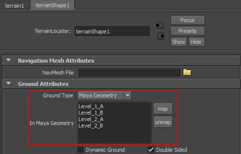
Note that if you are not using the Navigation or Goto Behaviors, you do not even need to provide a navmesh file for this terrain.
The terrain to be used during simulation is the one selected in the "In Terrain Mesh" attribute of the CrowdManager node.