


Layout Editor
LAUNCH
- Golaem Shelf:

- Golaem Render Menu: Simulation Cache Layout
- MEL Command: glmOpenCacheLayoutEditor;
- Stand Alone: ./scripts/glm/layout/layoutEditorStandAlone.py
SIMULATION CACHE LAYOUT GUI
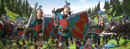
The Simulation Cache Layout Editor displays the information about the deformation applied to a Simulation Cache Proxy node.
It is composed of several parts:
Menu
 |
Open a new tab in the layout graph edition panel |
 |
Open a layout file in a new tab in the layout graph edition panel |
 |
Save Simulation Cache Layout file (.gscl) with the Deformation Layers added to the Layout Operations Panel for every Crowd Field of every Simulation Cache Proxy in the scene |
 |
Save As Simulation Cache Layout file (.gscl) with the Deformation Layers added to the Layout Operations Panel for every Crowd Field of every Simulation Cache Proxy in the scene |
 |
Clear the current tab in the layout graph edition panel |
 |
Change the settings of the Layout Tool |
 |
Synchronize selection with the DCC toggle button |
 |
Frame the Layout Graph Edition panel view to see all nodes |
 |
Frame the Layout Graph Edition panel view to see the current selection |
 |
Zoom the Layout Graph Edition panel view to the real size |
 |
Open the Simulation Cache Entity Inspector |
 |
Enable/Disable the Search Field panel |
 |
Enable/Disable the Node Library panel |
 |
Enable/Disable the Cache Status panel |
 |
Enable/Disable the Attribute Editor panel |
 |
The PLE indicator indicates that the Layout Editor is currently open with PLE license only. Any file saved from this session will become marked with PLE. This button is not displayed if the Layout Editor found a valid lite license. |
Nodes Library panel
This panel display the list of layout nodes that you can use to build your layout graph. Simply drag and drop them from the Layout Node Library to the layout graph edition panel.
 |
Note node to add a note in the layout graph |
 |
Entity Selector node |
 |
Group node to organize layout in sub graphs |
 |
Merge node to merge layout flows |
Transformation Layers
| Translate node to translate character's positions | |
 |
Rotate node to rotate character's orientations |
 |
Face to to make characters face toward a given point |
 |
Scale node to scale characters |
 |
Expand node to scale distance between characters |
Duplicate Layers
 |
Duplicate node to duplicate characters |
 |
SnapTo node to duplicate characters and snap them on Population Tool slots |
 |
CreateEntity to create an entity from a character file |
Visibility Layers
 |
Kill node to remove characters from the viewport and the rendering |
 |
Unkill node to restore characters to the viewport and the rendering |
Time Edition Layers
 |
Set Frame to set the frame data to use for characters |
 |
Frame Offset node to offset Simulation Caches for characters |
 |
Frame Warp node to warp Simulation Caches for characters |
Posture Edition Layers
 |
Posture node to edit the orientation of Character Bones |
 |
Rig node to import the Simulation Cache as a keyframed Maya skeleton and allow to edit curves |
 |
Look At to make characters look at a given point |
 |
BlindData to edit the blind data values (like blend shapes) |
 |
Ground Adaptation node to edit the ground adaptation mode |
 |
PlayAnimation to replay an animation file on an entity |
Trajectory Edition Layers
 |
Trajectory Vector Field node to constrain the trajectory of Characters to a Vector Field |
 |
Edit Trajectory node to edit the trajectory of characters |
Geometry Edition Layers
 |
Set Rendering Type node to edit the Rendering Type assigned to a Character |
 |
Set Mesh Assets node to edit the Mesh Asset assignment of a Character |
 |
Add/Remove Mesh Assets node to edit the Mesh Asset assignment of a Character |
 |
Replace Shader node to edit the Shader assigned to a Character Mesh Asset |
 |
Set Shader Attribute node to edit the Shader Attribute value assigned to a Character Shader |
 |
Set Attribute node to edit cache attribute values, that can be used in previz or rendering operations |
 |
Mirror Geometry node to mirror the geometry of a Character |
 |
Replace LOD Distances node to replace the lod distance of a Character file |
Layout graph edition panel
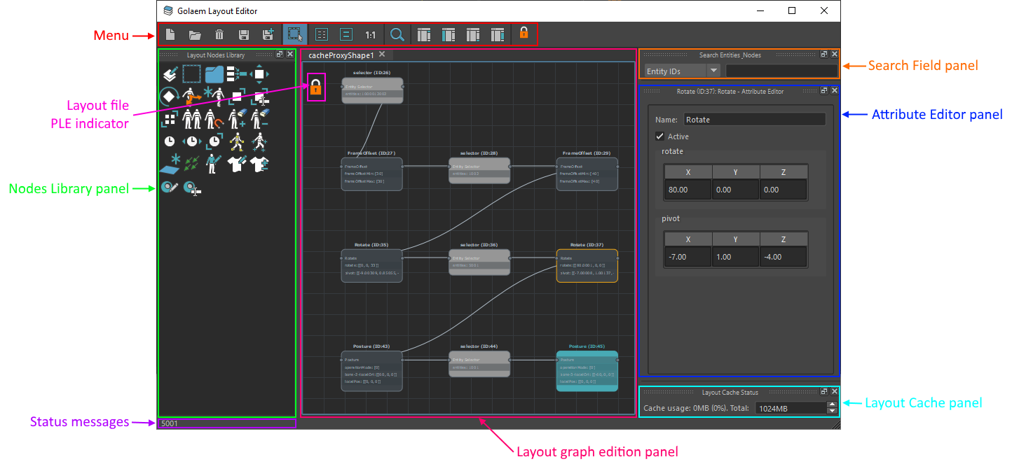
The layout graph edition panel is the place where you can edit the layout graph. Each tab represents a different layout graph. The tab can can be renamed by right clicking on the current tab:
Rename the current tab by right clicking on it
Understanding the graph
You can zoom in/out in the graph by using the mouse scroll.
You can pan in the graph by holding the Alt + mouse middle click while moving the mouse in the Layout Graph Edition panel.
Nodes
There are two kind of nodes:
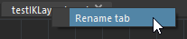
- 'selector' nodes changes the current selection of entities in the flow. They are represented in light gray:
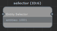
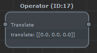
- 'operator' nodes perform operations on the currently selected entities in the flow. They are represented in dark gray:
Some nodes are both a selector and an operator: they perform an operation on the currently selected entities in the flow, but also changes the current selection of entities in the flow. This is for instance the case for the duplicate and snapTo nodes: they duplicate the currently selected entities while changing the selection to be the duplicates entities from now on.
Execution flow
The layout graph executes any node that contributes (is directly or indirectly connected on the left) to the root node (colored in cyan).
A node that is connected to the left of another node will always be executed first.
When a merge occurs, all nodes connected to the left of the merge node will be executed first, but there is no guaranty about the order in which it's going to be executed. If the order of execution matters, then nodes should be connected in the same single line of execution.
For instance, a layout graph that looks like this:
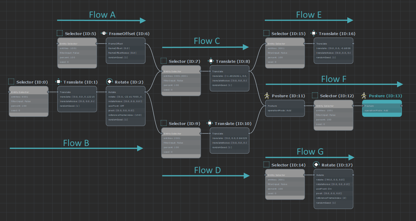
Will have the following execution flow:
- Flow A will be executed before flow C, but may be executed after D as it is not connected to its left
- Flow B will be executed before both flow C and flow D
- Flow C and D will both be executed before Flow F
- The Operator that is at the beginning of Flow F will use a selection that is a union of the selections from Flow C and D
- Flow F is executed last (as it includes the root node)
- Flow E will never be executed (it's not connected to the left of the Root node)
- Flow G will never be executed (it's not connected to the left of the Root node)
Automatic replacement of duplicate Ids with node output syntax
From Golaem 7.1 and higher, it is possible to stack several layouts on a cache. That implied a change in the duplicate entities ID management. As the duplicate IDs are a general pool, shared by the whole layouts stack, generating a new duplicate ID in a low index layout file, would shift all duplicate IDs of the higher indices ones. If the IDs are stored as they are generated, this could lead to a second layout file editing different entities onces the first one grow with more entities. To avoid that, the duplicate IDs of a layout are now automatically replaced by a syntax indicating that their are the output of a duplicate/snapTo node. This syntax is o([nodeId], [entityIndex]), standing for "output of node" nodeID, [entityIndex]th entity in node output. With that modification, all tweaks added to an entity duplicated in the same layout will stay consistent.
Editing the graph
Adding a node
- Drag and drop a node from the Layout Nodes Library
- Hit the 'tab' key in the Layout Graph Edition Panel, which will open a menu in the view:
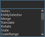
Type the node type name or simply select the node to add from the list to add it to the graph. - Use Maya translate / rotate / scale manipulators, while some entities are selected (in F9 mode). It will add a selection + node to the end of the root node with the current selection
- Double-click on a layout editor node in the shelf : if the selection is valid, it will add a selection + node to the end of the root node, else it will stack the node after the root node (if it exists). Double-clicking a selector node creates a selector with the current selection.
Removing a node
Select the node in the Layout Graph Edition Panel and hit the 'delete' key
Moving a node
- drag and drop the node in the Layout Node Library
- select the nodes to automatically layout and hit the 'L' key
Editing a node
- click on a node to show/edit the list of its parameters in the Attribute Editor panel
Check the meaning of each parameter directly in the node's documentation page
Connect/Disconnect nodes
To connect a node, you can:
- left click from one node plug to the other node's plug
- middle click from anywhere on the node to anywhere on the other node to connect
- move the node over an existing connection to insert the node between the two other connected nodes
To disconnect a node, you can;
- select a connection and hit the 'delete' key
- move the node to disconnect while holding the 'ALT' key
- use the cut tool by holding the 'ALT' key, while cutting the connection(s)
Set root node
Select a node and hit V key, or right click on the node and select the 'Set as root' option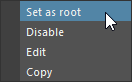
Grouping / Ungrouping nodes
Nodes can be grouped by selecting some nodes, then right clicking and clicking 'Group'. They can also be dragged and dropped on an existing group node, or copied from somewhere and paste in the group. Ctrl + G key also groups current selection under a new node.
Nodes can be ungrouped by selecting a group node, right clicking and clicking 'Ungroup'.
Navigation one step "up" from current group can be achieved with a Ctrl + double clic.
Misc
A node can be enabled or disabled by right clicking on it and selecting the 'Enable' or 'Disable' option.
Nodes can be copied/pasted:
- by using the Ctrl-C (to copy) and Ctrl-V (to paste) key shortcut
- by using the Ctrl-D (to duplicate) key shortcut
- by right clicking on the node(s) to copy and selecting the 'Copy' option, and then right clicking in the same Layout Graph Edition panel and selecting the 'paste' option
PLE indicators
There are two distinct PLE indicators () in the Golaem Layout Editor:
- one in the Menu, it is displayed only if no layout license was found, and indicates that any layout file saved with the editor will become PLE
- one in the Layout graph edition panel, it is displayed only if the opened layout file is already PLE.
Note that once a layout file is PLE marked, there is no way to un-PLE it, even with a valid license.
Please read the PLE license section in the documentation.
Renaming a tab
Tabs can be renamed by right clicking in the Layout Graph Edition panel or the opened tab and selecting the 'Rename tab' option
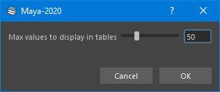
Settings
The settings panel allows to edit the Layout Tool global settings
Search Field panel
The selector panel allows to select entities or nodes by search string.
To select entities, set the selector to "Entity IDs", enter a search string, and hit enter. The resulting entities will be selected in the Maya scene. Examples of selection strings are:
- '1001' : directly select a single entity by its ID
- '1001,3001': select several entities by their ID
- '1001-3001': select a range of entities
- 'et(0)': select all entities of type '1'
- 'cf(1)': select all entities that were simulated in a crowdfield index '1'
To select nodes, set the selector to "Node Names", enter a search string, and hit enter. The resulting node(s) will be selected in the Layout graph edition panel. You can use the '*' wildcard whenever searching for a partial string (for instance, 'SnapTo' won't find the node named 'mySnapTo', while '*SnapTo' will).
Attribute Editor panel
The attribute editor panel is the place where you can edit the parameters of layout nodes.
To edit a node's parameter, simply select the node you want to edit in the Layout graph edition panel, and the Attribute editor panel will display the parameters that can be edited.
Layout Cache panel
This panel displays the amount of RAM that is currently used by the Golaem Cache. Whenever the cache is full, old frames in cache will be dropped to add new frames.
Status Messages
This line will display the currently selected entities in Maya.
Layout Editor Display Level of details
The editor can use three different display modes, depending on the zoom level, to keep if fast and readable.
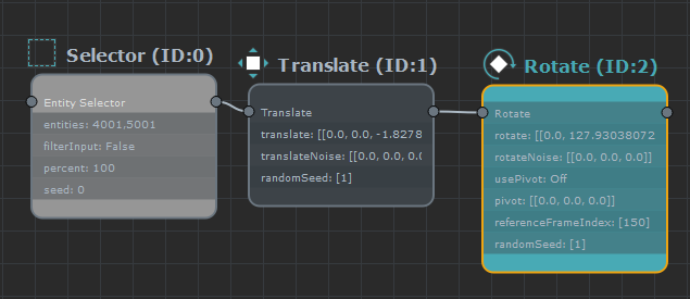
While the editor is focused on a few nodes, the level of detail is maximum, showing each node parameter and its value.
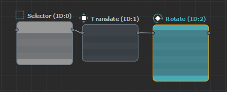
When the editor is being zoomed out, the parameters are not displayed anymore to (performance saving) as they are not readable anymore.
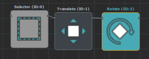
When zoomed out further, the title logo starts to be unreadable, and is moved in a bigger version, displayed inside of the node, which helps to keep track of what are the transformation types of each node.