


Skeleton Tab Overview
Golaem Crowd uses a dedicated animation engine, which can automatically retarget, blend and mix motions on any kind of morphology. To perform these features, the animation engine uses its own representation of characters and motions. The morphology of a character is stored in the Golaem Character File (*.gcha), which is used in Entity Type nodes during a crowd simulation. The Skeleton Tab allows to convert a Maya skeleton (joint hierarchy) into the Golaem Crowd skeleton format.
The Skeleton Tab is also the place where you can edit the character's physical properties, as well as more advanced features like bones excluded from the inverse kinematics computation (IK). For more information on these features, see the Character Maker Main Concepts page. Note that bones excluded from IK can also be defined for each Skeleton Mapping Node in the Main Workspace, along with roll bones.
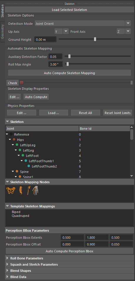
Golaem Character Maker - Skeleton Tab
The information shown in this tab is relative to the Character File displayed in the active tab of the Main Workspace. To start using the Skeleton Tab you have to either load a character file or load a skeleton from a Maya joint hierarchy (see below).
Loading a Skeleton (Maya Joint hierarchy)
You can access this feature through:
- Skeleton Tab: Load Selected Skeleton button
This command only works if a joint node is selected in Maya, otherwise a warning message will be displayed in Maya's Script Editor. Keep in mind that the joint hierarchy must comply with Golaem Crowd's Character Prerequisites.
The skeleton is built starting from the joint that is selected in Maya as root of the skeleton. In most cases, it's the top most joint in the hierarchy that you need to select.
Once the skeleton is loaded according to the Detection Mode (see below), the skeleton bone hierarchy is displayed in the Skeleton view (see below) and in Maya's viewport through the Character Maker Locator node, allowing you to check that it was properly detected.
Reloading a Skeleton
The skeleton of an existing Skeleton Mapping can be reloaded without breaking the mapping. This is especially useful when creating Skeleton Mappings for different morphologies that have a similar structure. To access this feature, press the Load Selected Skeleton button when a Skeleton Mapping already exists. Three options are available (see image below):
- Remap by name: the bones of the new skeleton are remapped by name. If there are any missing bones, a warning message that lists the missing bones will be displayed, allowing to either continue or create a new mapping
- Remap by bone id: the bones of the new skeleton are remapped by id. If the skeleton hierarchies are different, a warning message will be displayed, allowing to either continue or create a new mapping
- Create New Mapping: creates a new empty Skeleton Mapping from the selected Maya skeleton
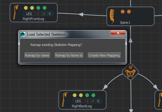
Reloading a skeleton on an existing Skeleton Mapping
Once the remapping is done, it's also possible to change the Skeleton Options (see below).
Skeleton Options
The skeleton options allow to configure the general properties of the skeleton.
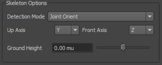
Skeleton Options
Detection mode
This parameter determines how to detect the skeleton pose from the joint hierarchy. Three modes are available:
| Joint Orient |
The skeleton detection process will only consider the joint orient values of each joint, but the transform values won't be used. For more information, see Maya's documentation: User Guide / Rigging / Character Setup / Character Setup Menus / Skeleton / Orient Joint. |
| Bind Pose | The skeleton detection process uses the bind pose (more exactly, it uses the maya skin clusters nodes). It is the pose used in the skinning process. For more information about the bind pose, see Maya's documentation: User Guide / Rigging / Character Setup / Skinning / Bind pose. |
| Current Values | The skeleton detection process uses the local values of the joints at the current time, as a combination of the "Transform Attributes" and the "Joint Orient" |
The Detection Mode is taken into account when loading the skeleton from Maya, but can be changed afterwards as long as no Skeleton Mapping is done. The detected skeleton is considered valid if the skeleton pose displayed by the Character Maker Locator node closely matches Maya's joint display.
Character Axes
| Up Axis |
The character's up axis. It should be the character's vertical direction, usually from its feet to its head. In most cases this is Maya's Y axis. |
| Front Axis |
The character's front axis. It should match the character's front facing direction. In most cases this is Maya's Z, X, -Z or -X axis. |
Use the Character Maker Locator node to check that the character axes were correctly set.
Warning: it is crucial to set the Character Axes correctly, otherwise Motions cannot be extracted and replayed correctly.
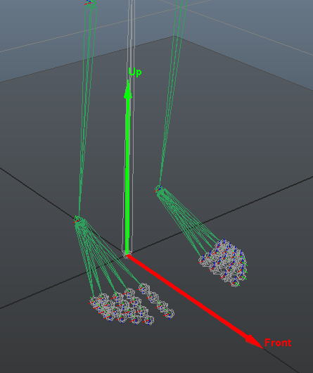
Character Axes
Ground Height
This is the height of the ground of the character in Maya world coordinates. The ground is represented by the Character Maker Locator node as a grey plane. It should be adjusted so that it touches the bottom of the character's feet geometry (which can be different from the bottom of the skeleton). The Ground Height is used by the animation engine to correctly adapt the feet to the ground.
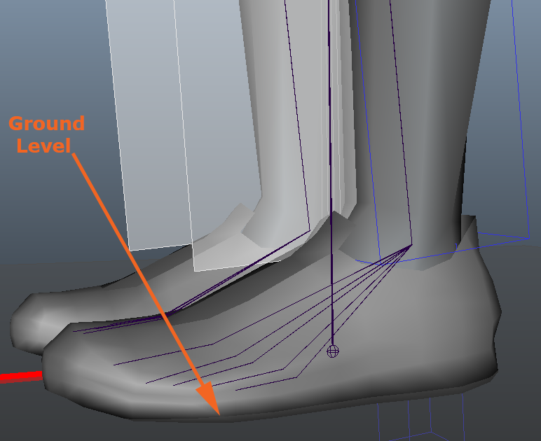
Example of a correct value for Ground Height
Automatic skeleton mapping
This command analyzes the skeleton morphology and detects the structure of the skeleton. It creates the matching nodal representation of the skeleton in the Main Workspace and maps it to the skeleton. The accuracy of the Skeleton Mapping depends on the skeleton morphology, some adjustments might be needed.
Due to the human morphology specificity (Two legs, two arms and one head), the automatic skeleton mapping process is especially accurate on biped skeletons.
You can access this feature through:
- Skeleton Mapping Tab: Auto Compute Skeleton Mapping button
- Character Maker Menu: Auto Compute Skeleton Mapping action in the Skeleton Mapping menu
This feature only becomes available once a skeleton is loaded. If a Skeleton Mapping is present, it will be replaced by the one computed automatically.
The Automatic Skeleton Mapping has the following parameters:
| Auxiliary Detection Factor |
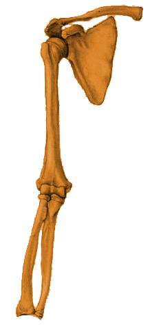
This factor is only used on grasper Limbs, to detect the difference between auxiliary and extension bones in the case where additional bones (usually bones excluded from IK or roll bones) could prevent a correct detection. On the bone chain of a Limb or Effector node, if there is a bend with an angle greater than the mean bone chain bend angle increased by the Auxiliary Detection Factor (Bend Angle > Mean Bend Angle + Mean Bend Angle * Auxiliary Detection Factor), then the bones before this bend are detected as auxiliary bones, and the rest of the bones in the chain as extension bones (see image below). |
| Roll Max Angle |
Bones in the middle of a bone chain that bend less than this angle are considered as bones excluded from IK, and thus they can be used as roll bones (see Character Main Concepts page). |
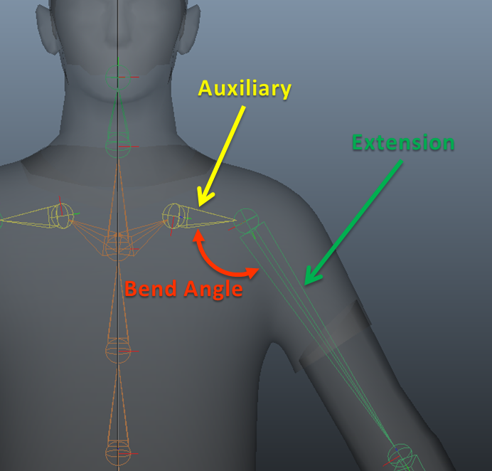
Auxiliary Detection Factor: bone bend angle is great enough to detect an Auxiliary bone chain
Check skeleton mapping
This option allows to check the conversion of bones from the Golaem Crowd internal representation to the source skeleton.
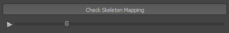
Check Skeleton Mapping
To preview the conversion of the skeleton mapping, click on the Check Skeleton Mapping button. A slider changing the Limb Length Ratio appears and is
played to try different sizes for all your limbs. The result is exposed on the Character Maker Locator.
Skeleton Display Properties
The Skeleton Display Properties define the appearance of the character in Skeleton Shapes display mode. Each skeleton bone is represented by a shape that can be edited manually or computed automatically from the character skinning information.
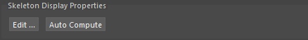
Skeleton Display Properties Window
To edit the Skeleton Display Properties manually, click on the Edit... button, which will open the Skeleton Display Properties window.
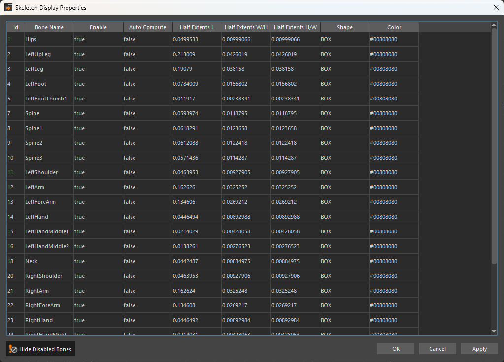
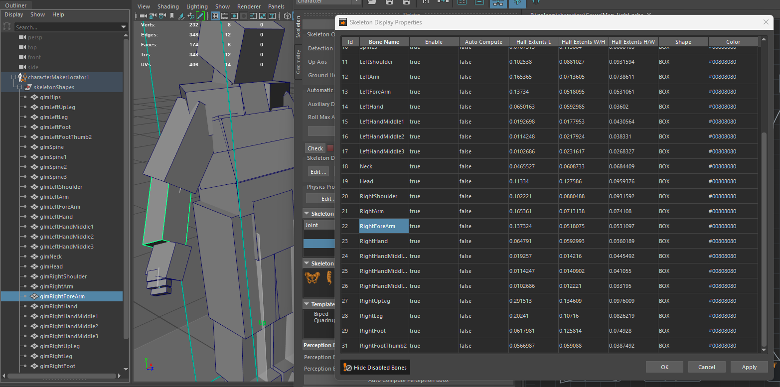
The Skeleton Display Properties window allows to edit all skeleton shapes in a table view. To edit a property of a bone, double click the wanted value in the row matching the bone, change its value and hit the Enter key or select another cell, and then click the OK or Apply button. The skeleton shapes are also displayed as Maya primitives in the viewport under the Character Maker Locator. The Maya shapes can be translated, rotated and scaled directly in the viewport and the changes will be taken into account as soon as the character file is saved. Selecting a bone in the Skeleton Display Properties window will also select its shape in Maya and vice versa.
To edit multiple properties at the same time (the same property for multiple bones):
- select the wanted cells by left click-dragging the mouse over them or by clicking on a column or by clicking on multiple cells using the Ctrl key to add or remove a single cell to the selection or the Shift key to add or remove a range of cells to the selection
- double click on one enabled cell in the selection while holding the Ctrl key to avoid deselecting the other cells, change its value and hit the Enter key or select another cell to apply the same value to all the selected cells
- click on the OK or the Apply button to see the changes in the viewport
Hide the disabled bones by clicking on the  button.
Parameters
| Id | Displays the id of the bone in the Skeleton. All the properties on the same row belong to this bone. | |
| Bone Name | Displays the name of the bone in the Skeleton. All the properties on the same row belong to this bone. | |
| Enable | When set to true, the shape is displayed for this bone. | |
| Auto Compute | When set to true, the shape position, size and orientation is computed automatically based on the character skinning information. The shape is also set to BOX. To see the changes in the viewport, click on the OK or Apply button. | |
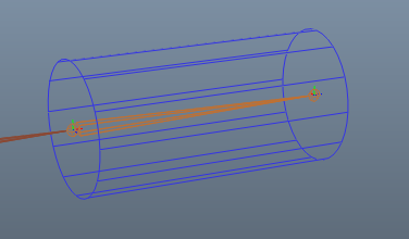
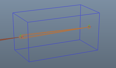
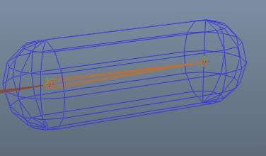
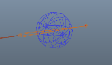
| Half extents L/W/H | Defines the size of the skeleton shape using distances from the center of the shape to its borders, or half extents, on each axis - Length (L), Width (W) and Height (H). This means that the total size on an axis is twice the half extent. To see the changes in Maya's viewport, on the Character Maker Locator node, click the OK or Apply button. | |
| Shape | Shape of the bone representation. There are 4 possible shapes: Cylinder / Box / Capsule / Sphere | |
| Color | Color of the bone. When left unchaged, the color of the Entity Type is used. The color of the bone is blended with the Entity Type color based on the Display Color Weight. | |
Automatic Skeleton Display Properties
To compute the Skeleton Display Properties automatically, either click on the Auto Compute button to do this for all the bones, or set the Auto Compute property to true in the Skeleton Display Properties window for the desired bones and click on the Apply or OK button.
The auto compute uses the meshes loaded in Maya that are skinned to the joints of the skeleton, or if the skeleton and joints are not loaded in Maya it uses the geometry file as a fallback.
It is best to first finish the Skeleton Mapping (see above) before running the Skeleton Display Properties auto compute, as the skeleton mapping can influence the final result (especially the IK normal planes).
Physics Properties
See the Bone Physics Properties section.
Skeleton view
This view displays the bone hierarchy of the character skeleton, as detected from the Maya joint hierarchy. Each bone matches a Maya Joint and has a Bone Id, which may be used in several behaviors: Look At Behavior, IK Behavior, Constraint Behavior. When selecting a bone in this view, it's also highlighted on the the Character Maker Locator node, and the Character Maker Node to which it is mapped (if any) is selected in the Main Workspace.
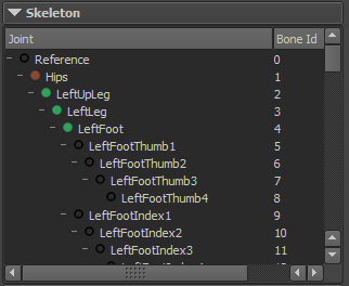
Skeleton View
An icon displays the mapping status of each bone:
 |
The bone is not mapped |
 |
The bone is mapped to the Pelvis |
 |
The bone is mapped to a Spine |
 |
The bone is mapped to a Limb as an auxiliary |
 |
The bone is mapped to a Limb as an extension |
 |
The bone is mapped to an Effector as an auxiliary |
 |
The bone is mapped to an Effector as an extension |
Skeleton Mapping Nodes View
This view provides access to the nodes that are used to define the Skeleton Mapping. To use a node, drag and drop it into the Main Workspace.
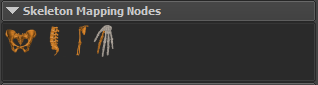
Skeleton Mapping Nodes View
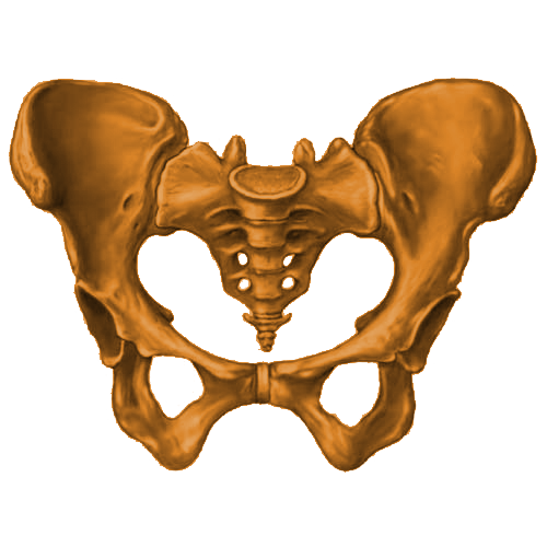 |
Pelvis |
Defines the pelvis of the character. A valid Skeleton Mapping must have one and only one Pelvis node |
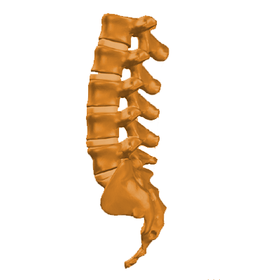 |
Spine | Defines a spine of the character. A Spine must be connected to another Spine or to the Pelvis. The Skeleton Mapping can contain any number of Spine nodes |
 |
Limb |
Defines a limb of the character. A Limb must be connected to a Spine or to the Pelvis. The Skeleton Mapping can contain any number of Limb nodes |
 |
Effector | Defines an effector of the character. An Effector must be connected to a Limb. The Skeleton Mapping can contain any number of Effector nodes |
For more information on each node type, see the Main Workspace page.
Template Skeleton Mappings View
This view provides a list of available predefined Skeleton Mappings. To use a template, drag en drop it into the Main Workspace. This will create the node structure, and the nodes will then have to be mapped manually.
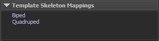
Template Skeleton Mappings View
A template can only be used if the Main Workspace is empty (i.e. usually after loading a skeleton from Maya).
Biped Template
This template fits most biped humanoid characters. It uses two Limbs for the legs, each with one Effector for the toes, two Limbs for the hands, each with five Effectors for the fingers, and one Limb for the head. Once the Skeleton Mapping is created from the template, the node structure can be modified to fit specific character morphologies.
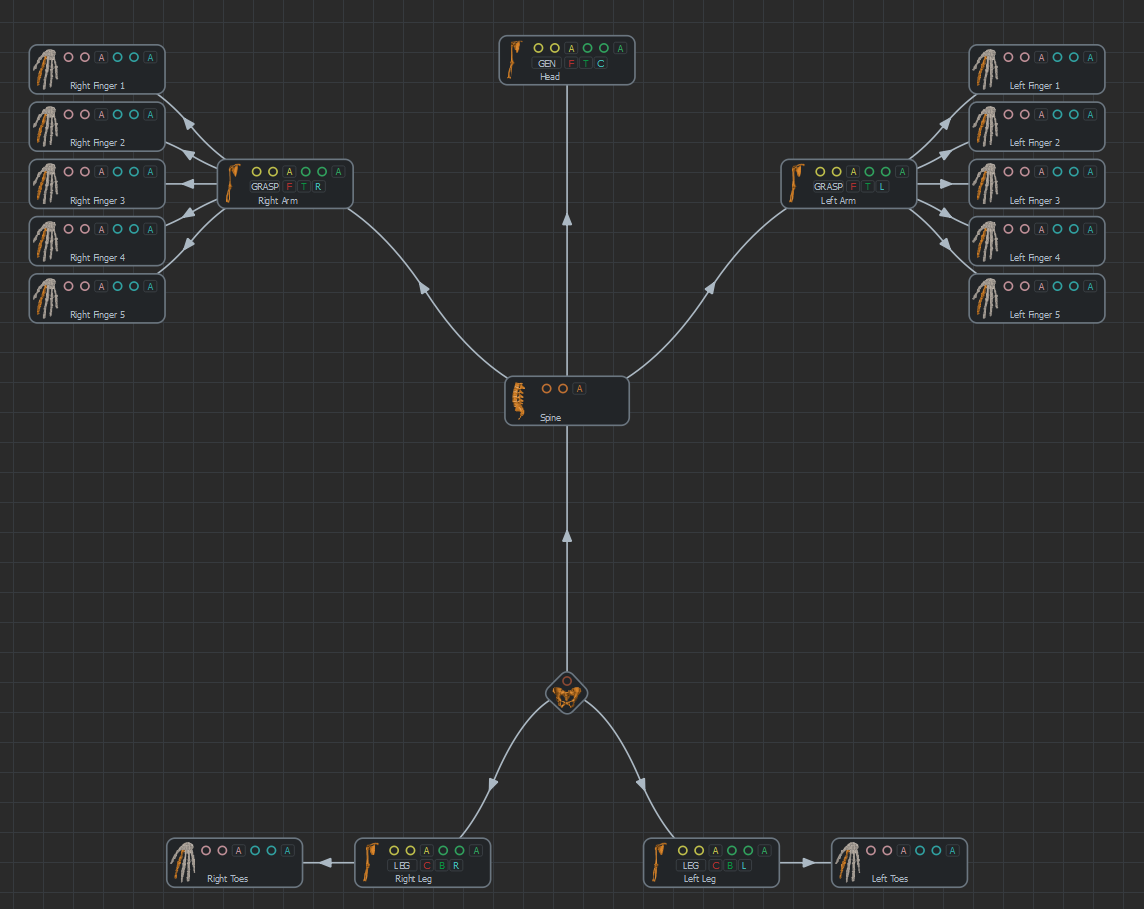
Biped Template Skeleton Mapping
Quadruped Template
This template fits most quadruped characters. It uses four Limbs for the legs (two front legs and two back legs), each with an Effector, a Limb for the head and a Limb with an Effector for the tail. Once the Skeleton Mapping is created from the template, the node structure can be modified to fit specific character morphologies.
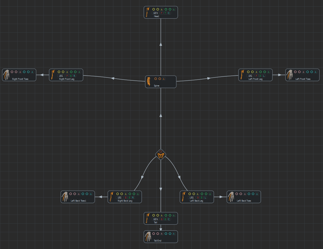
Quadruped Template Skeleton Mapping
Perception BBox Parameters view
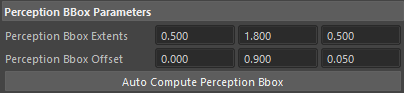
Perception BBox Parameters
These parameters define the default Perception Shape of the character as a bounding box. The Perception Shape can be overridden with any geometry in the Entity Type node Perception Attributes.
The Perception Shape is voxelized and the voxels that approximate it are what the Sensors can detect. The amount of voxels is defined by adjusting the Max Voxel Per Axis parameter in the Entity Type node Perception Attributes. The voxels that approximate the Perception Shape are also used in the Navigation and Go To behaviors. To visualize the voxels during the simulation, enable Display Entities on the Perception Locator.
| Perception Bbox Extents | The size of the default perception box along each axis. |
| Perception Bbox Offset | Offset from the root bone of the character to the center of the perception box. |
| Auto Compute Perception Bbox | Computes the perception box automatically (Perception Bbox Extents and Perception Bbox Offset). The result is the bounding box of all the bones except the bones mapped to a grasper Limb, to avoid boxes that are too big because the character is in T-pose or A-pose. |
To display the perception bounding box, enable Show Perception BBox the on the Character Maker Locator node.
Roll Bone Parameters view
This view allows to define which bones are excluded from IK (see the Character Main Concepts page for more information on bones excluded from IK).
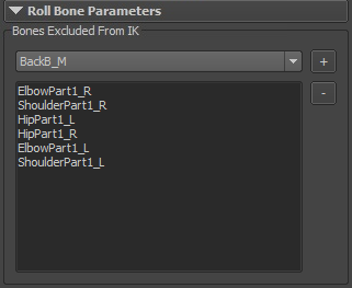
Roll Bones Parameters View
The Skeleton Mapping should be finished before using this view, as the list of available bones depends on it. To exclude a bone from IK, select it in the combo box and click on the + button. The bone will be added to the list below. To remove bones from this list, select them and click on the - button. The pose displayed by Character Maker Locator may update if a motion is loaded.
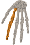
Squash And Stretch Parameters view
This view allows to define how the Squash'n Stretch ratios are applied to the scale of their related bone at rendering, and also in Render Previz display mode (see the Character Main Concepts page for more information on Squash'n Stretch).
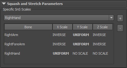
Squash And Stretch Parameters View
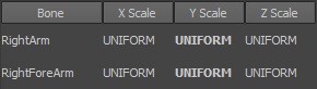
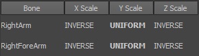
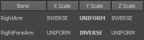
By default, a Squash'n Stretch ratio is applied uniformly on all axis of the related bone. To specify a particular distribution on a given bone, select it in the combo box and click on the + button. The bone will be added to the list below, with the value UNIFORM set for each axis. These specified axis are the axis of the bone local coordinate system, and the one displayed in bold is the axis closest to the bone direction (e.g. the vector from this bone to its child bone). Each axis must be applied any of these value (by double-clicking on it):
- UNIFORM: Apply scale on this axis with value equal to the bone Squash'n Stretch ratio
- INVERSE: Apply scale on this axis with value equal to the square root inverse of the bone Squash'n Stretch ratio
- NO SCALE: Do not apply scale on this axis (scale with a value of 1.0 in fact)
 |
 |
 |
 |
 |
 |
Example of Squash'n Strech axis distributions for a streched right arm animation
To remove a bone from this list, select it and click on the - button. Default setup is then used for this bone, e.g. UNIFORM parameter for each axis.
Bone Physics Properties
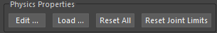
The Skeleton Mapping Tab also allows to configure the physical properties of the skeleton, which impact the way characters react when using the Physicalize and Force behaviors. There are several ways to configure the properties:
- The "Edit..." button allows to opens the Physics Properties dialog and manually configure all shapes;
- The "Load..." button allows to copy the configuration from another .gcha file. A dialog prompting from which file and how to remap the physics properties will be displayed:
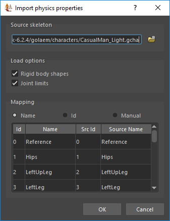
You need to first select the source file from where copying the physics properties, and then the mapping option by name, id, or manual mapping. - The "Reset All" button will automatically reset both the physics shapes (disable physics shapes on extensions, configure size on other bones) and angular limits of the ragdoll (computed according to the IK plane configuration).
- The "Reset Joint Limits" will automatically reset the angular limits of the ragdoll without modifying the physics shapes.
It is advised to use the Ragdoll Maya Primitives to fine configure the physics properties of a character, as explained here.
Physics Properties Dialog
The Physics Properties Dialog allows to edit all physical properties of the Skeleton in a table view. To edit a physical property of a bone, double click the wanted value in the row matching the bone, change its value and then hit the Enter key or select another cell.
To edit multiple properties at the same time (usually the same property for multiple bones):
- select the wanted cells by left click-dragging the mouse over them or by clicking on a column or by clicking on multiple cells using the Ctrl key to add or remove a single cell to the selection or the Shift key to add or remove a range of cells to the selection
- double click on one enabled cell in the selection while holding the Ctrl key to avoid deselecting the other cells, change its value and hit the Enter key or select another cell to apply the same value to all the selected cells
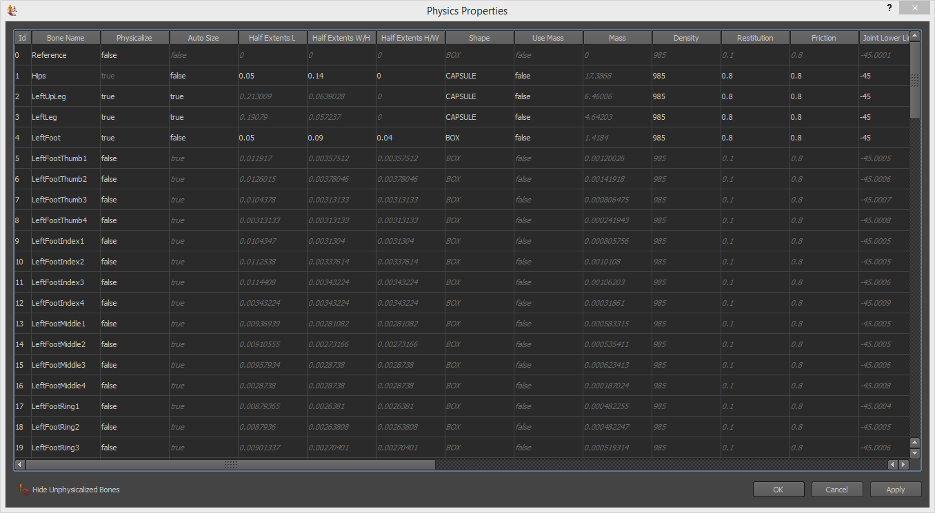
Physics Properties Dialog
Hide the unphysicalized bones by clicking on the button.
Notice that the Physics Properties Dialog allows to sort columns value by clicking on a column header.
Parameters
| Id | Displays the id of the bone in the Skeleton. All the properties on the same row belong to this bone. | |
| Bone Name | Displays the name of the bone in the Skeleton. All the properties on the same row belong to this bone. | |
| Physicalize |
When enabled, the bone has a physical representation defined by all the other parameters, and takes part in collisions as a rigid body attached to the rest of the bone hierarchy. When disabled, the bone has no physical representation, thus it doesn't take part in the physical simulation. No property applies in this case. Physicalized bones have an impact on crowd simulation performance when using the Physicalize and Force behaviors, thus to increase performance you can disable this property for unneeded bones. |
|
| Auto Size | When enabled, the size of the physical shape is computed automatically based on the bone length, otherwise you can enter the size of the shape manually | |
| Half extents L/W/H |
Defines the size of the physical shape using distances from the center of the shape to its borders, or half extents, on each axis - Length (L), Width (W) and Height (H). This means that the total size on an axis is twice the half extent. To see the changes in Maya's viewport, on the Character Maker Locator node, click the Apply button. |
|
| Shape |
Shape of the physical representation. There are 4 possible shapes:
|
|
| Use Mass | Edit the Mass of the physical shape instead of the Density. You can only edit either the Mass or the Density of the shape, the other one is deduced using the volume of the shape. | |
| Mass | Mass of the physical shape, in kg. You can only edit either the Mass or the Density of the shape, the other one is deduced using the volume of the shape. | |
| Density | Density of the physical shape, in kg/m³. You can only edit either the Mass or the Density of the shape, the other one is deduced using the volume of the shape. | |
| Restitution | Ratio of energy restituted when colliding (between 0 and 1) | |
| Friction | Ratio of energy lost when sliding (between 0 and 1) | |
| Linear Damping | Ratio of linear velocity lost per second (between 0 and 1). | |
| Angular Damping | Ratio of angular velocity lost per second (between 0 and 1) | |
| Joint Lower Limit X/Y/Z | Lower bound of joint rotation around each axis in the joint's local coordinate system, relative to the skeleton pose (between -360° and +360°) | |
| Joint Upper Limit X/Y/Z | Upper bound of joint rotation around each axis in the joint's local coordinate system, relative to the skeleton pose (between -360° and +360°) | |
| Color | Color of the bone, can be used in Collision Triggers. The standard color to avoid collision is grey (128,128,128). | |
Blend Shapes
This view lists all the blend shapes that are connected to the joint hierarchy of the character.
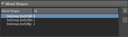
Blend Shapes view
Each blend shape line in the Character Maker represents a weight of a Maya blend shape node (see image below).
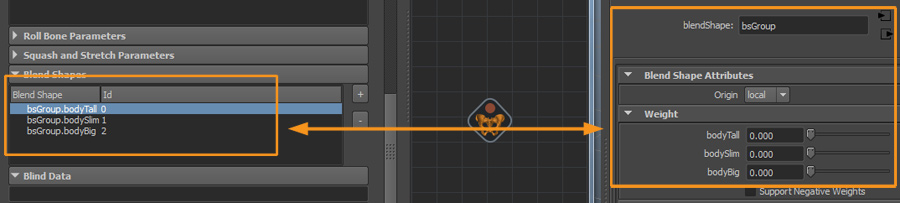 Blend Blend Shapes in the Skeleton Tab and its matching Maya blend shape node in the Attribute Editor
Blend Shapes are automatically detected when loading a Skeleton from a Maya joint hierarchy. To reset the Blend Shapes, use the Load Selected Skeleton button (see Loading A Skeleton).
To add one or more blend shape groups manually, select one or more blend shape nodes in Maya and click on the "+" button. They cannot be added twice. To remove a blend shape group, select it in the Blend Shapes view and click on the "-" button.
Notice that during simulation (either in Behaviors, Channels...), Blend Shapes will be considered as Blind Data (see below).
Blind Data
This view lists all the float Maya attributes that will be stored along a Character.
It's important to notice that those attribute values will be stored as *blind* data. It means that, even if they will be handled, blended and exported by Golaem, they will not be automatically used at rendering time. It's the user responsability to make use of those (either connecting them to a Shader Attribute or using the Plug Output of the Simulation Cache Proxy).

Blind Data View
Blind Data needs to be manually added to the Blind Data text field in the form "mayaNodeName.mayaNodeAttribute" separated with "," (see image below):
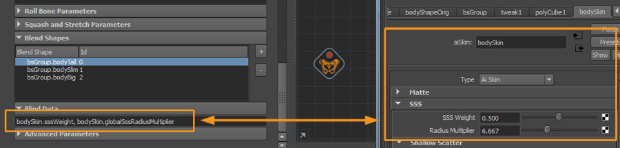
Blind Data in the Skeleton Tab and the matching Maya attributes in the Attribute Editor