


Converting Skeleton
As of August 5th, 2025, Golaem will no longer provide direct support.
All support for Autodesk Golaem will now be handled exclusively through Autodesk support channels and this website will be deactivated soon.
Please bookmark the Autodesk Golaem Support section for any future support needs related to Autodesk Golaem packages.
Golaem Crowd uses a dedicated animation engine, which can automatically retarget, blend and mix motions on any kind of morphology. To perform these features, the animation engine uses its own representation of characters and motions. It consists of two steps:
This skeleton conversion is done using the Skeleton Tab of the Character Mode in the Character Maker.
Defining the Golaem Skeleton
We demonstrated this step in a Golaem Live! video. It comes as a complement of other information below.
Loading The Maya Skeleton
Golaem Crowd uses a dedicated animation engine, which can automatically retarget, blend and mix motions on any kind of morphology. These features can only be performed because it uses its own skeleton for internal computation. However it does not mean that you have to use the Golaem Crowd skeleton only. You just need to create a mapping between your characters' skeleton and the Golaem Crowd one. This mapping is created thanks to the Character Mode of the Character Maker and stored as a part of the Character File (.gcha).Once generated, this file will be referenced by the Entity Type.
- Load your character in Maya (here we will use the /golaem/shaders/CMO-man_golaemMR.ma scene from the Samples Pack) and load Golaem Crowd. The sample characters consists on some overlapping meshes (organization to be detailed later) skinned on a skeleton.
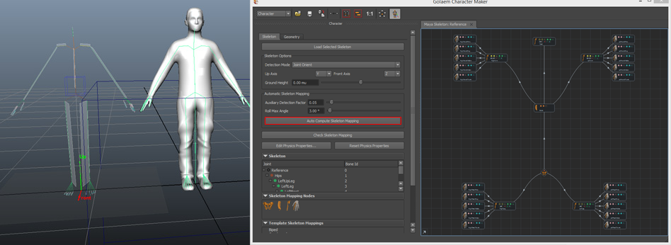
- Select the root bone in the Maya Outliner, open the Character Maker and click on the Load Selected Skeleton button in the Skeleton Tab.
Note that if several bones could be considered as the root of your skeleton, you should always choose the bone which will place/scale your character in the scene. This root bone can possibly be the child of other bones, but these parent bones should not rotate/translate/scale the character. Otherwise when simulating or rendering you could face unexpected results.
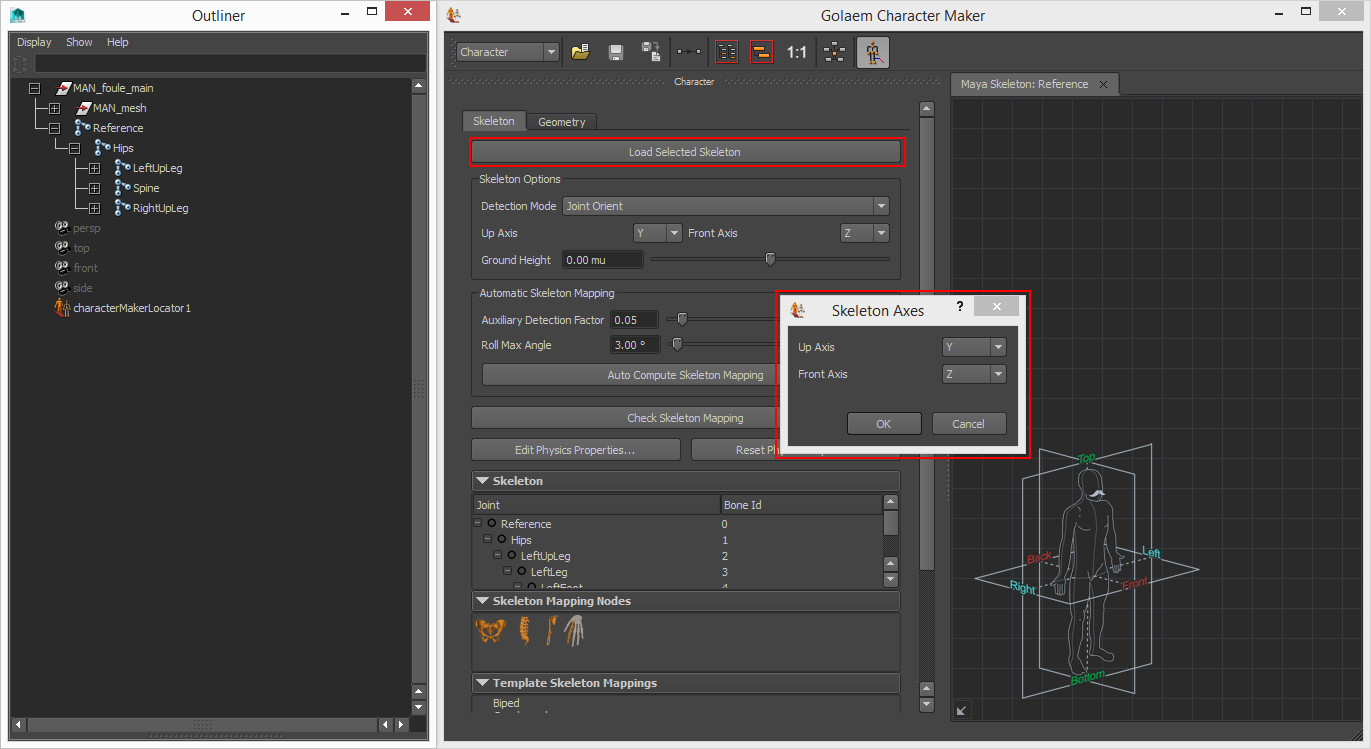
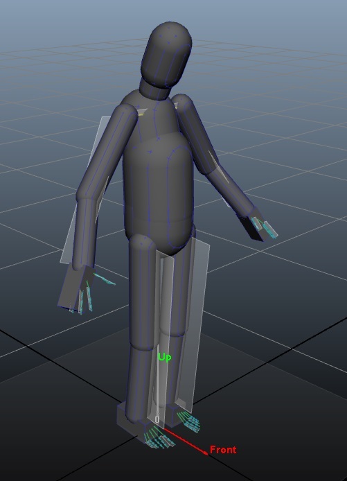
- A dialog pops up, asking to define the axis the character is facing. Check your Maya viewport to see if they are correct or should be fixed:
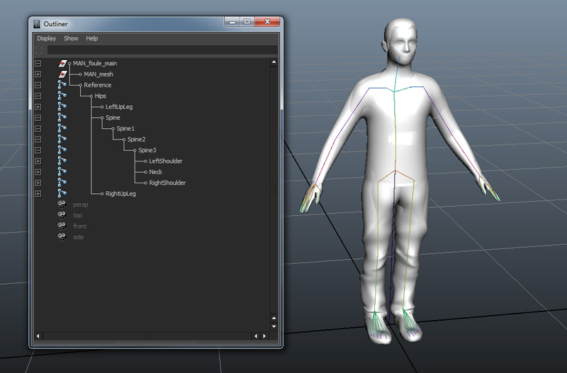
If you cannot see the Character Maker Locator, make sure your display parameters are correct (Show/Locators should be checked). Also note that you can control the bones size of the Character Maker Locator with the usual Display / Animation / Joint Size dialog.
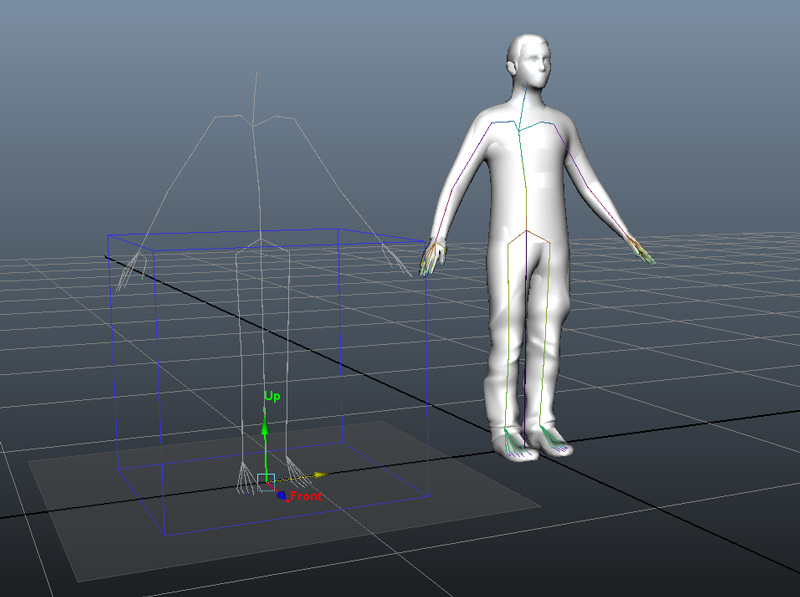
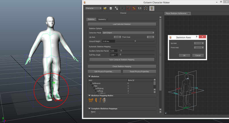
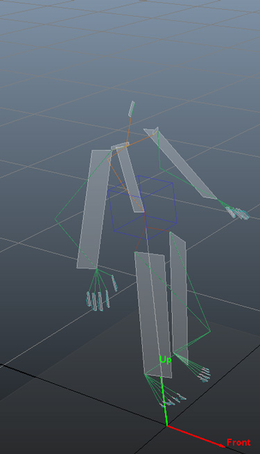
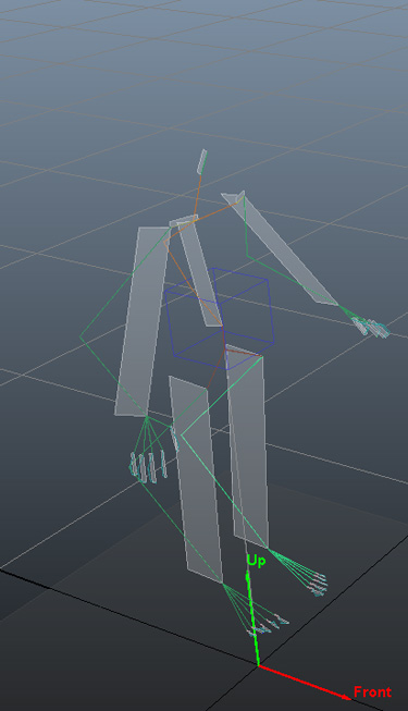
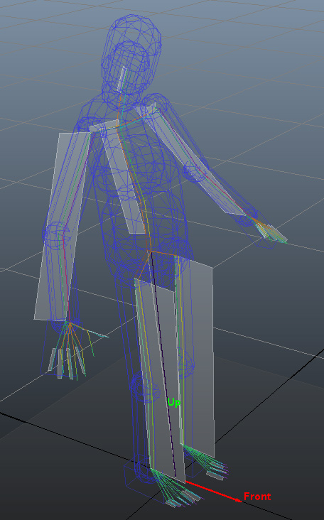
- If the skeleton is correctly detected, the Character Maker Locator should show something similar to your source character (but not necessarily in the exact same pose, like in the below screenshots). If the skeleton is not correctly detected, you can change the detection method (see here for a description of each method). Note that several detection modes can give a result considered as correct, although different from the others. The best detection mode is the one that give the closer result to the recommendations given for Character Prerequisites.
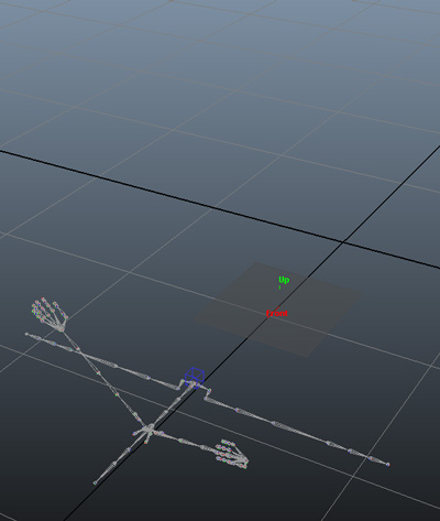
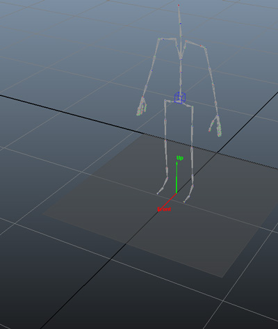
Left: Character Maker Locator showing an incorrecly detected skeleton - Right: The same skeleton correctly detected.
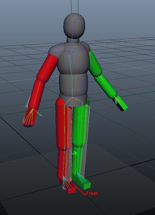
- You will also notice a gray plane under the Character Maker Locator. It represents the Ground Height, and should be adjusted so that it touches the bottom of the character's feet geometry (which can be different from the bottom of the skeleton). The Ground Height is used by the animation engine to correctly adapt the feet to the ground.
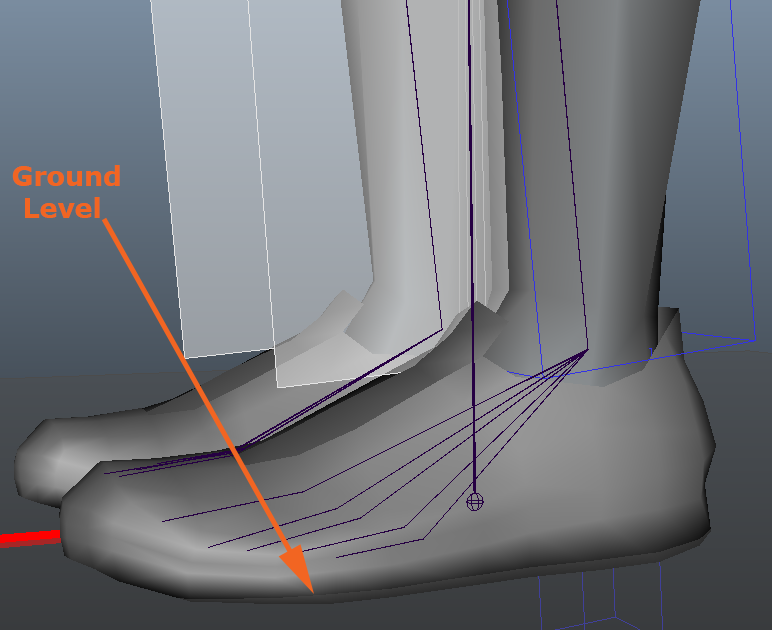
Example of a correct value for Ground Height
Creating the Skeleton Mapping
- When the Skeleton Options are correctly set, you can click on the Auto Compute Skeleton Mapping to automatically create the Golaem Crowd Skeleton Nodes in the workspace and map them to your skeleton. It also creates IK Normal Planes (white planes on the Locator).
Check the Skeleton Mapping
Global Structure
After the skeleton mapping nodes have been generated, you should check in the workspace that:
- a root node has been created
- this root node is connected to a spine
- a correct number of limbs (e.g. arms, legs...) have been detected and connected to either root or spine
- a correct number of effectors (e.g. fingers) have been detected and attached to their respective limbs
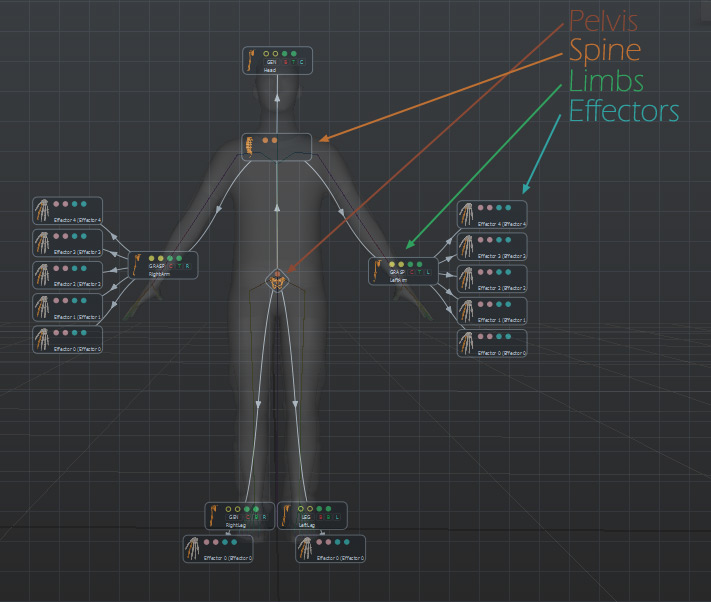
Example of a correct Skeleton Mapping
You can check the Character Main Concepts for a definition of each node and what they represents in most common characters. See Character Maker Main Workspace for a precise definition of each node, and Character Maker Controls to know how to add/remove or link nodes.
Check Bone Mapping
After having checked if the global structure of the character is correct, you need to check that each Skeleton Mapping Node is mapped to the correct bone. Bone mapping relies on the concept of Extension and Auxiliary Bone Chains
- Example of an Human Bone Mapping
- Example of an Horse Bone Mapping
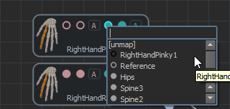
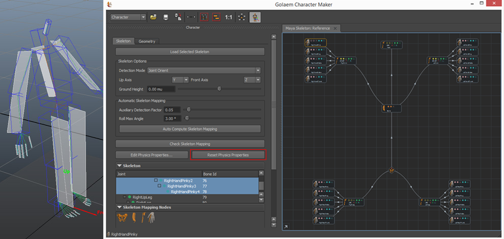
- Select a finger to highlight its mapped bones in the joint list (you can also used the tooltips on each circle).
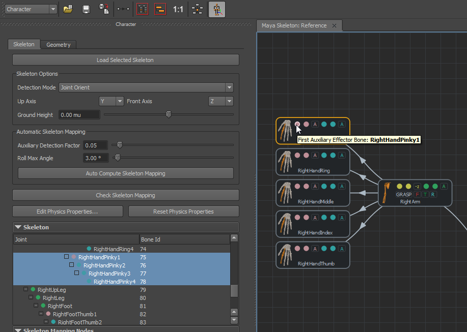
- Unmap both auxiliary bones, and map RightHandPinky1 as the first extension bone.
 |
 |
- The same process should be repeated for each fingers.
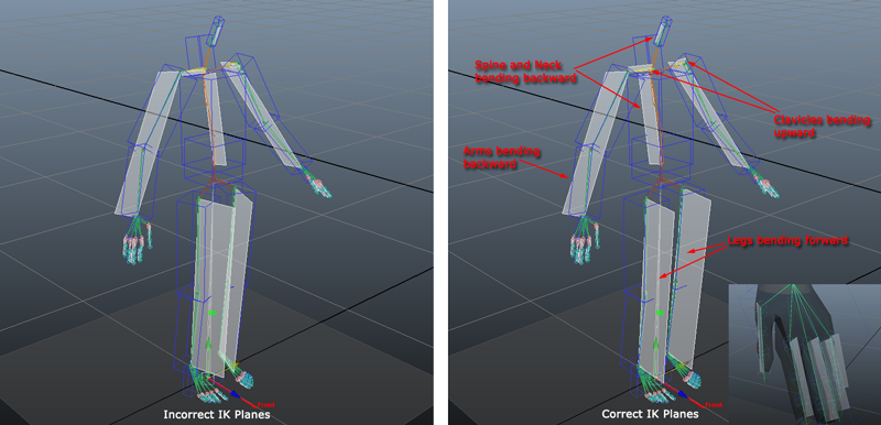
Check IK Normal Planes
IK Normal Planes define in which direction the bones chains bend. They're displayed as white plane in the Locator.
It is important to check they are correctly defined before saving the Character File. As the IK Normal Planes definition strongly depends on how the skeleton has been defined, there is no absolute rule. However, the following example meet the most common skeleton setup for a human:
IK Normal Planes can be easily set by clicking on the related toggle boxes.
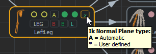
In the example above (left), we only have extension bones mapped, so we must select the good IK Normal Plane. We often prefer let our brain at rest and try these combination  /
/ (+/-1, 0, 0),
  /
/ (0, +/-1, 0) or
  /
/ (0, 0, +/-1) which works in 99% of the cases.
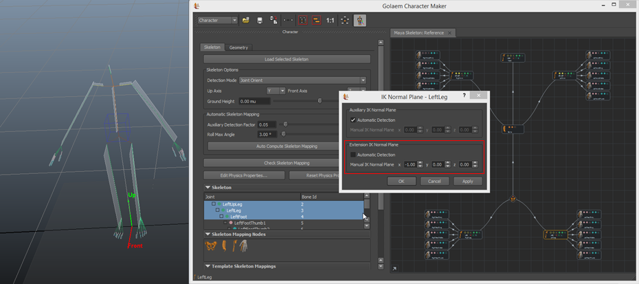
For more specific IK Normal Planes values, use the IK Normal Planes dialog by right-clicking on the related limb and selecting Edit IK Normal Planes.
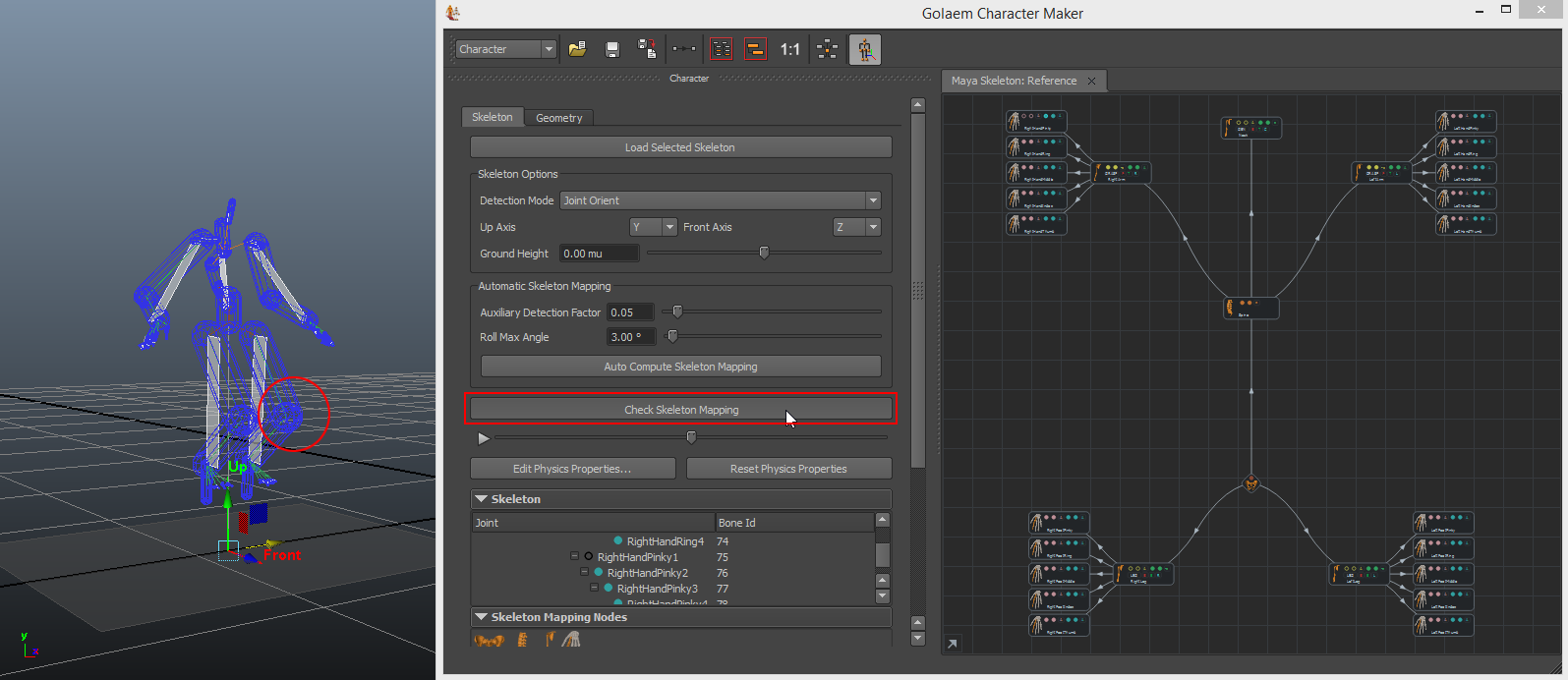
- There is a tool to help you to check if the limbs IK planes are correctly defined or not. Click on Check Skeleton Mapping button.
 |
 |
|
| Conversion Preview on the defaut Automap IK planes, knees do not bend parallely | Conversion Preview with knees IK planes defined backward. Correct for an animal, but definitely not for a human... |
Check Roll Bones or Bones To Be Excluded From IK
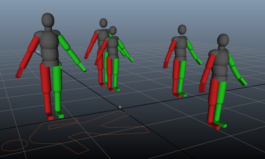
If some bones should not be taken into account by Golaem Crowd (because they are just helpers, roll bones, or here for legacy reasons...), they should be excluded from the Inverse Kinematic (IK) computation. Otherwise, when playing a motion on the skeleton, Golaem Crowd may attribute a part of the motion to these bones and give an unwanted result (see an example below).
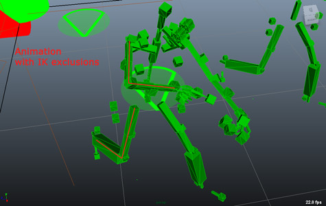
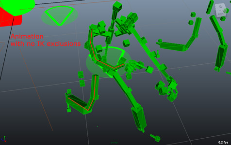
Left: Animation with IK Exclusions on arms and legs - Right: Animation with no IK Exclusions on arms and legs.
See Bone excluded from IK and Roll Bone for more details.
See the Character Maker Main Workspace to know how to exclude a bone from IK, or to declare a bone as roll bone.
Saving The Character File
The Character File (*.gcha) is now ready to be saved (Character Maker Toolbar / Save ) and can be load in an Entity Type for a Crowd Simulation or to import motions in the Character. However if you plan to use it in Physics Simulation, you should proceed to the next step.
Defining the Character Physics Properties
This is a quick setup, see here for a full test and setup tutorial.
You may have noticed a couple of blue shapes around each bone of the Character. Those shapes are the Character Physics Shape taken into account in the physics simulation.
- To enhance this you can use the Reset Physics Properties button. It will autocompute a Physics Shape for the most meaningful bones.
- You can translate the CharacterMaker Locator back on top of your character to check if it fits it correctly.
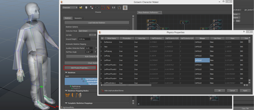
- Use the Edit Physics Properties button to load a spreadsheet representing all bones and their physical properties. Double click in a cell to edit it. Before being able to edit a bone properties, this bone should be physicalized (physicalize property = true), and to be able to modify its size, the autosize property should be set to false (but let forget about the size at this step, it will be configured later). In the example below, you can notice that we used a big box on the hand bone representing all fingers. As physics simulation is a computation expensive, it is better not to physicalize all finger if it is not needed.
See the Reference Guide for Bone Physics Properties for more details about them.
- Now that the Physics Shapes are correctly chosen for each bone, let's fine configure the dimensions and positions of each one. Select the Character maker locator, and make sure the "Show Ragdoll Maya Primitives" is set to true:
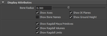
The physics shapes should now be present as Maya Polygons:
Left: Default Physics Shape Display - Middle: Physics Shape as Maya Primitives - Right: Edited Primitives
You can now directly use the Maya objects to change the properties of the Character Physics Shape, and ensure it fits at best the character's geometry:
Result of a simulation using the Character File defined above (Display mode in the Entity Type is set to Physics Shape)
- Do not forget to save your Character File again after editing the physics properties
If the Mirror button in the Character Maker Tool Bar is selected, and the limb has a mirror mapping configuration, the modification on the rigid body will also affect the mirrored bone.