


Main Workspace (Skeleton)
When in the Character Mode, in the Skeleton Tab, the Main Workspace displays the Skeleton Mapping as a node-based graphical interface. It allows to create a new Skeleton Mapping or edit an existing one.
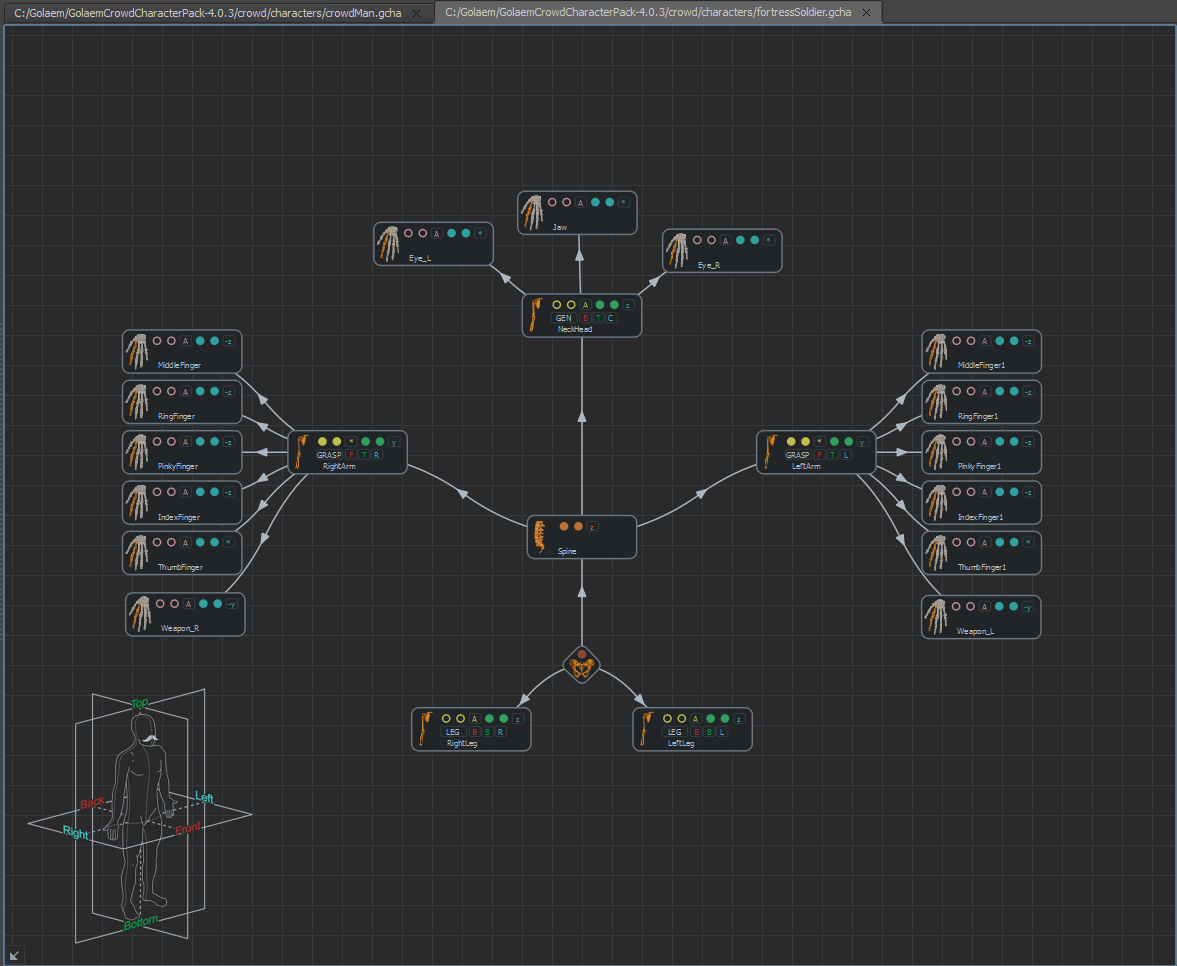
Character Maker Main Workspace - Skeleton
You can open more than one Character files or Motion files at the same time, each one being displayed in its own tab. When no Character or Motion file is open, a message prompts to either load a Character File (*.gcha), a skeleton from Maya, or a Motion File (*.gmo). Each one of these actions will open a new tab in the Main Workspace.

Workspace tabs
Skeleton Mapping Nodes
To add a node, drag and drop it from the Skeleton Mapping Nodes view in the Skeleton Tab, or press the TAB key inside the Main Workspace and select the node to add. Nodes must be linked together in order to be mapped to bones, otherwise the mapping has no effect. To link two nodes, draw a link by dragging the mouse while holding the middle button, or use the link button  on the toolbar. See the Character Maker Controls page for more information.
Notice: The Skeleton Mapping should respect the character's joint hierarchy. A bone in Golaem Skeleton Mapping should be parented to the very same bone in Maya.
There are four types of Skeleton Mapping nodes:
| Name | Icon | Main Workspace Representation | Description |
| Pelvis | 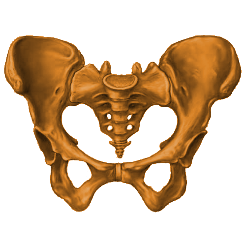 |
 |
Defines the pelvis of the character. A valid Skeleton Mapping must have one and only one Pelvis node. The Pelvis is the root node of the Skeleton Mapping. A single bone can be mapped to the Pelvis. |
| Spine | 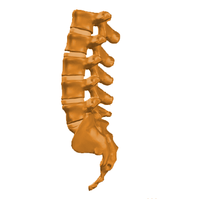 |
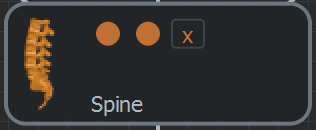 |
Defines a spine of the character. A Spine must be connected to another Spine or to the Pelvis. The Skeleton Mapping can contain any number of Spine nodes. A Spine can be mapped to a single bone chain. The relative IK Normal Plane can be changed with the Ik Normal Plane toggle box NameThe name of the Spine can be set by right-clicking it and choosing Rename... . |
| Limb | 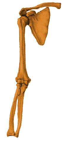 |
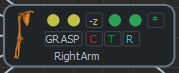 |
Defines a limb of the character. A Limb must be connected to a Spine or to the Pelvis. The Skeleton Mapping can contain any number of Limb nodes. A Limb can be mapped to two bone chains: an auxiliary bone chain (yellow) and an extension bone chain (green). Only the extension bone chain needs to be mapped be mapped, the auxiliary is optional. IK Normal Planes can be changed with Ik Normal Plane toggle boxes. TypesThere are 3 possible Limb types, defined with a toggle box:
LocationThe location of the Limb, relative to the Pelvis, can be specified through 3 toggle boxes, along the 3 anatomical planes (see below). NameThe name of the Limb can be set by right-clicking it and choosing Rename... . The name of the Limb also defines the name of the Motion Channel to which it belongs. |
| Effector | 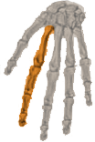 |
 |
Defines an effector of the character. An Effector must be connected to a Limb. The Skeleton Mapping can contain any number of Effector nodes. An Effector can be mapped to two bone chains: an auxiliary bone chain (pink) and an extension bone chain (blue). Only the extension bone chain needs to be mapped, the auxiliary is optional. IK Normal Planes can be changed with Ik Normal Plane toggle boxes.
NameThe name of the Effector can be set by right-clicking it and choosing Rename... . |
Bone Mapping
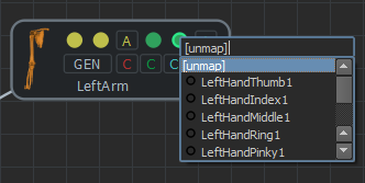
A Skeleton Mapping is only valid when its nodes are mapped to bones. It's recommended to connect a node all the way to the Pelvis and map all its ancestor nodes before mapping it. To map a bone to a node, click on a bubble item and select the bone from the popup list. The popup lists unmapped bones first, in a hierarchical order, starting from the last mapped bone in the node or in it's parent node.
Bone mapping popup, example on a Limb
Another way to map a bone is to drag it from the Skeleton view in the Skeleton Tab, and drop it on a bubble item on a node.
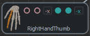
To have an overview of the mapped bones of a node, select it in the Main Workspace. This will select the mapped bones in the Skeleton view in the Skeleton Tab, and highlight them in the Character Maker Locator node.
To unmap a bone, click on its bubble item in the node and select [unmap] from the popup.
Bone unmapping
Some helpers are available to map bones differently once mapped. These are accessed by right clicking on the node:
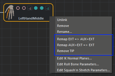
Right click on a node to get mapping helpers
| Remap EXT => AUX+EXT | Will remap the first bone of the extension chain to the first bone of the auxiliary chain and will automatically find a new mapping bone for the last bone of auxiliary chain and first bone of extension chain. |
| Remap AUX+EXT => EXT | Will remap the first bone of the auxiliary chain to the first bone of the extension chain and will remove all mapping for the auxiliary part. (useful for correctly remapping the fingers of a character after an automating mapping) |
| Remove TIP | Will replace the last bone of the extension chain by its father bone (useful for removing TIPs on fingers nodes) |
When a selection is active, these helpers will apply to the whole current selection (when applicable)
If the Mirror button in the Character Maker Tool Bar is selected, and the limb has a mirror mapping configuration, the modification on node will also affect the mirrored node.
Once mapped, the node will show it's current status thanks to its outline color:
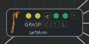 |
Status: normal. The node will be correctly saved in the file. |
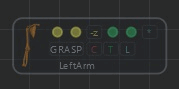 |
Status: unconnected. The node is not connected (directly or indirectly) to the root, and won't be save. |
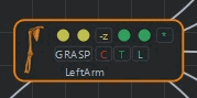 |
Status: warning. The node mapping will be save as desired and should work in simulation, but the mapping is not optimal and requires some attention. |
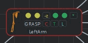 |
Status: warning. The node mapping will not be save because it would not work in simulation. |
Anatomical Planes
The anatomical planes are three reference planes centered on the Pelvis that are used to define the location of a Limb Node (and of its Motion Channel). These locations are useful when auto computing the Motion Mapping, and are also used to automatically layout the nodes in the Main Workspace. They are represented in the Anatomical Planes HUD in the bottom left corner of the Main Workspace. The HUD changes to show the current plane when hovering over a location toggle box in a Limb node. To hide the HUD, click on the  button. To restore it, click the button again.
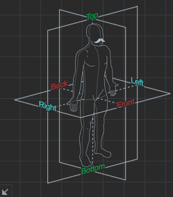
Anatomical Planes HUD
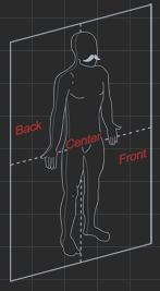 |
Coronal planeDivides the body into a front portion and a back portion. On a Limb, the locations relative to this plane are:
|
Transverse planeDivides the body into a top portion and a bottom portion. On a Limb, the locations relative to this plane are:
|
|
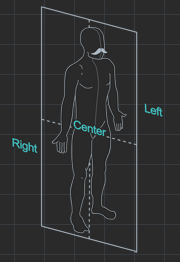 |
Sagittal planeDivides the body into a left portion and a right portion. On a Limb, the locations relative to this plane are:
|
 Center
 Front
Front Back
Back Automatic
 Center
 Right
Right Left
LeftIK Normal Planes
For the IK Normal Planes concepts see the Character Main Concepts.
IK Normal Planes can be edited directly on spine nodes, limb nodes and effector nodes with the Ik Normal Plane toggle boxes. By default Golaem Crowd will automatically detect the IK Normal Plane. To edit the IK Normal Planes of multiple nodes at once, select the nodes and Shift+click on the desired toggle box.
 Automatic detection
 User defined Ik Normal Plane (Set with the Ik Normal Plane dialog)
 /
/ (+/-1, 0, 0) Ik Normal Plane
 /
/ (0, +/-1, 0) Ik Normal Plane
 /
/ (0, 0, +/-1) Ik Normal Plane
IK Normal Planes should be aligned on the rotation axis as shown in the image below:
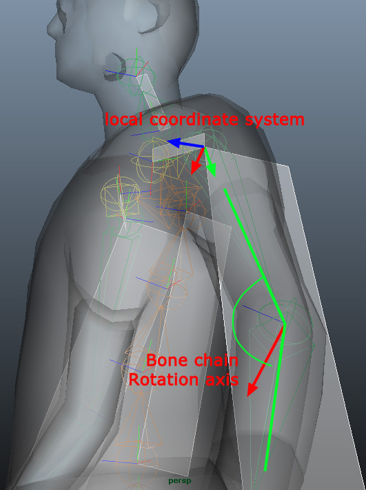
If a detected plane looks wrong it can be manually set using the IK Normal Planes toggle boxes. In the example above the detected orientation on the elbow joint must be applied to the shoulder local coordinate system.
Please note that the coordinate are local to the edited bone and should be set to either / (+/-1, 0, 0), / (0, +/-1, 0) or / (0, 0, +/-1).
To edit IK Normal Planes and set the normal with specific values right-click on a node to show the context menu and then select Edit IK Normal Planes to open this dialog:
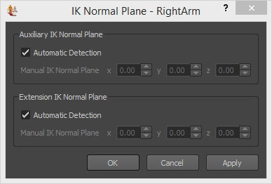
IK Normal Planes Dialog on the RightArm limb
Clicking on Apply allows to immediately see the result on the Character Maker Locator without closing the menu.
For more intuitive editing, use the Check Skeleton Mapping button. Now change the Ik plane values and hit Apply to see an immediate effect in the viewport. For more details on conversion preview see Conversion Preview
Bones Excluded From IK / Roll Bones
For the Bones Excluded From IK & Roll Bones concepts see the Character Main Concepts.
To edit Bones Excluded From IK & Roll Bones right-click on a node to show this menu:
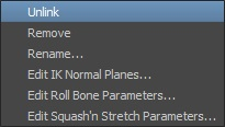
Node contextual menu
Then select Edit Roll Bone Parameters to open this menu:
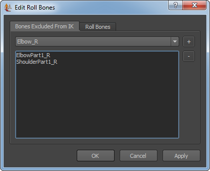
Bones Excluded From IK tab
The Bones Excluded From IK tab shown above permits to exclude roll bones from IK, as explained in the Character Main Concepts.
The Roll Bones tab shown below allows to select a bone to define the degree to which each target roll bone is influenced when you rotate the associated character limb. The Roll Value is extracted from the first bone, e.g. Wrist_R, and applied to the bones in the parent hierarchy (e.g Elbow_R and ElbowPart1_R), according to the given weights.
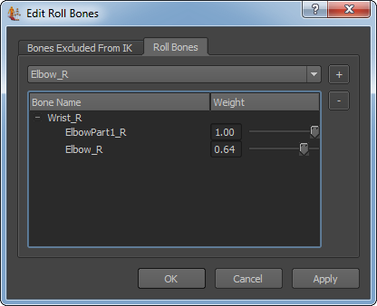
Roll Bones tab
Roll weights can be positive, or negative if the roll bone rotate in the other way than the one on which the roll is extracted.
Squash'n Stretch
For the Squash'n Stretch concepts see the Character Main Concepts.
To edit Squash'n Stretch parameters right-click on a node to show this menu:
Node contextual menu
Then select Edit Squash'n Stretch Parameters to open this menu:
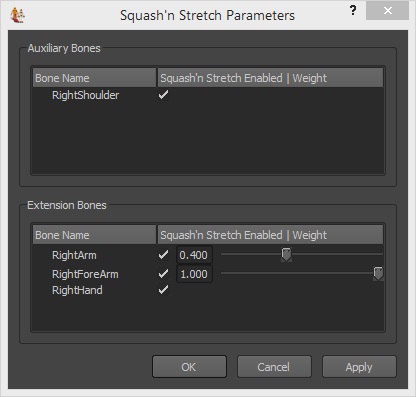
Squash'n Stretch Parameters Dialog
The Squash’n Stretch Parameter dialog shown above is available for a spine, limb or effector node and aims at configuring Squash’n Stretch on the bones which are part of the related auxiliary and extension bones chains:
- When converting a Squash’n Stretch animation: only the bones enabled are taken into account to compute at each animation frame the amount of Squash’n Stretch associated to the auxiliary or extension bone chain;
- When replaying a Squash’n Stretch animation on a character: the amount of Squash’n Stretch computed for each frame and associated to the auxiliary or extension bone chain is applied only on the bones enabled and distributed according to the weights set on the enabled bones.
Be careful when replaying a Squash’n Stretch animation on a character whose Squash’n Stretch parameters are different from the ones setup for the character used to convert the animation. Enabling or disabling bones differently at conversion/replay may lead to undesired position of the bone at the end of the bone chain. However, modifying the weights will only affect replay (not conversion) and can be done at any time.
- The bone at the end of the auxiliary /extension bone chain (as the Squash’n Stretch distribution can only be done among the bones inside the bone chain);
- The unique bone inside the bone chain, if it consists only of one bone (as the Squash’n Stretch can only be applied on this bone).
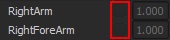
Squash’n Stretch can take into account or skip a bone by enabling or disabling its check boxe.If enabled, a bone can be set a relative weight using its numeric field and slider.
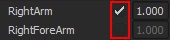
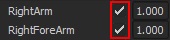
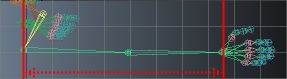
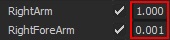
Enabling bones and setting weights determines how the Squash’n Stretch is distributed over the bones of a bone chain. For instance, considering stretch on the right arm of a human morphology (with a right arm bone affected by a 1.2 scale and a right forearm bone affected by a 1.5 scale):
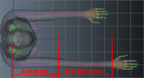
Stretched arm bone chain, composed of a arm bone scaled by 1.2 and a forearm bone scaled by 1.5
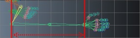
Enabling or disabling bones affect the total amount of squash/stretch computed for the entire bone chain. In this example, it influences the length of the entire arm, e.g. the resulting position of the hand bone relatively to the position of the arm bone:
 |
 |
No stretch |
 |
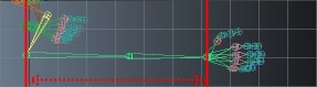 |
Stretch from arm bone only |
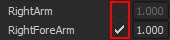 |
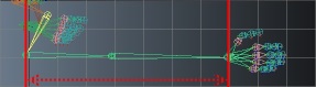 |
Stretch from foream bone only |
 |
 |
Stretch from both arm and forearm bones (same as input) |
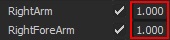
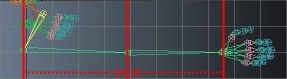
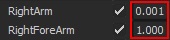
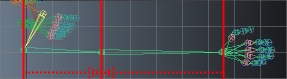
Setting weights only affect how the amount of squash/stretch is distributed over the bones that composed the bone chain (without affecting the total length of the bone chain). In this example, it influences only the position of forearm bone (without affecting the position of the hand bone):
 |
 |
Stretch applied on both arm and forearm bones uniformly (default parameters) |
 |
 |
Stretch applied only on arm bone |
 |
 |
Stretch applied only on forearm bone |
 |
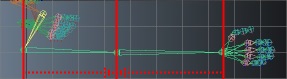 |
Stretch applied on both arm and forearm bones accurately (same as input) |
Mirror Mapping
Mirror mapping is needed in order to be able to replay a mirrored motion file in the Motion or the Locomotion behaviors. Mirror mapping defines for each Spine, Limb and Effector, the source Spine, Limb or Effector from which to replay the mirrored Motion.
To access this feature, right-click on a Spine node or on a Limb node and select Edit Mirror Mapping... from the context menu:
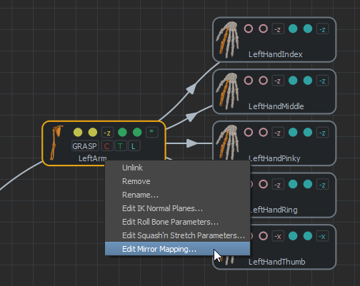
Edit Mirror Mapping menu on a Limb node
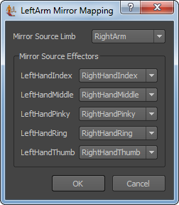
Mirror Mapping dialog for a Limb node (LeftArm)
Limb and Effector Parameters
| Mirror Source Limb |
The Limb node from which to play the mirrored Motion. It should not be left empty unless you don't want to replay any mirror animation on the Limb. For Limbs that don't have an equivalent (like the head of a character), the Limb should be mapped to itself. |
| Mirror Source Effectors |
For each Effector of the selected Limb, the Effector node from which to play the mirrored Motion, among the Effectors of the mapped Limb. If left empty, no mirror animation will be played on it. |
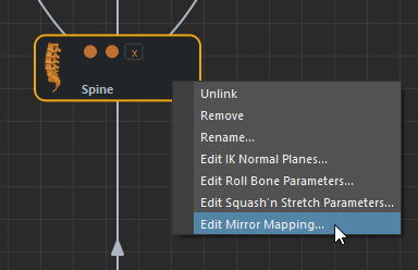
Edit Mirror Mapping menu on a Spine node
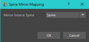
Mirror Mapping dialog for a Spine node (Spine)
Spine Parameters
| Mirror Source Spine |
The Spine node from which to play the mirrored Motion. It should not be left empty unless you don't want to replay any mirror animation on the Spine. For Spines that don't have an equivalent or that are unique, the Spine should be mapped to itself (by default, each Spine node is mapped to itself) |