


Navigation And Locomotion
As of August 5th, 2025, Golaem will no longer provide direct support.
All support for Autodesk Golaem will now be handled exclusively through Autodesk support channels and this website will be deactivated soon.
Please bookmark the Autodesk Golaem Support section for any future support needs related to Autodesk Golaem packages.
Creation
-
Behavior Editor / Behavior Library:

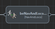
- Golaem Menu: Crowd Behaviors / Behaviors / CrowdBe NavAndLoco Node
- MEL command: glmCrowdBeNavAndLocoCmd;
Best Practices
As the NavAndLoco Behavior may blend any pair of Motion Clip in its set, it is recommended to only use Motion Clips with the same style. For instance, if there is one motion with arms up and another with arms down, the character will constantly move arms up and down as a side effect of the locomotion, which is usually not expected.
In such a case, two different NavAndLoco Behaviors (one for arms up, the other one for arms down) should be created, and the switch between the two made when desired by using a trigger.
Best practices for the creation of the motion set are described here.
Configuration
Motion Attributes
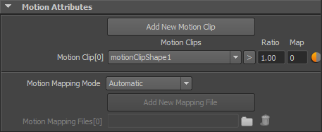
| Locomotions Files (.gmo file) |
Motions Clips to use in the NavAndLoco System.
Notice that the provided Motion Clips need to define a root translation and/or delta orientation (used to compute the original velocity of the motion). See the Motion Tab of the Character Maker or the Motion Clip attributes to see how to ensure Motions are correct and edit them.
|
| Motion Mapping Mode / Motion Mapping File |
This attribute allows a choice of four motion mapping modes :
|
 icon to
  to load the mirrored animations,
  to load both original and mirrored animation). It is recommended when you don't have both the turn-left and turn-right motions. In this case, use the
  icon to enable / disable a Motion Clip without removing it from the behavior.
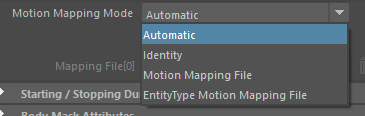
Starting / Stopping Duration Attributes
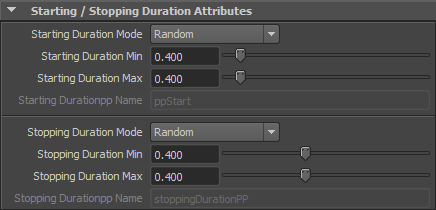
| Starting / Stopping Duration Mode |
This attribute allows a choice of two modes :
The Starting / Stopping Duration value is in seconds. |
| Starting / Stopping Duration Min |
See Random option of the Starting / Stopping Duration Mode above Available only when the Starting / Stopping Duration Mode is set to "Random" |
| Starting / Stopping Duration Max |
See Random option of the Starting / Stopping Duration Mode above Available only when the Starting / Stopping Duration Mode is set to "Random" |
| Starting / Stopping Durationpp Name |
Name of the float per-particle field of the relative particle system, containing the Starting / Stopping Duration Mode value which will be used (for more explanation about how to use ppAttributes, see ppAttributes Handling) Starting / Stopping Duration value is set to 0 if the ppAttribute name is empty or invalid Available only when the Starting / Stopping Duration Mode is set to "Per-Particle Attribute" |
Body Mask Attributes
By default, a motion is played on the entire body (as specified in the Motion Mapping File). But the Motion Mapping File configuration can be filtered by the body mask to replay the animation only on specified channels.
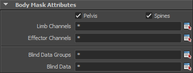
Body Mask Attributes of a Motion Behavior
| Pelvis | If this box is checked, the pelvis part of the motion will be played. The pelvis part includes the global position and orientation of the animation. If not checked, the animation will be played "in place" |
| Spines | If this box is checked, the spines parts of the animation will be played on the entity |
| Limb Channels |
List of the limbs channels to play on the entity. Use the |
| Effector Channels |
List of the effectors channels to play on the entity. Use the  button to open a window with the name of all the available Effectors for the Character Files loaded in the scene. Those names can also be found in the Motion Mapping Panel of the Character Maker. button to open a window with the name of all the available Effectors for the Character Files loaded in the scene. Those names can also be found in the Motion Mapping Panel of the Character Maker.Star ( * ) wildcard is authorized at the beginning or/and end of names (i.e. left*, *arm, etc.). Separate the channel names by comma ( , ), leading and trailing spaces will be ignored. Use the * wild card to use all effectors. If an effector channel is selected, the corresponding limb channel is automatically added also. Names are NOT case sensitive (compared as lowercase). |
| Blind Data Groups |
List of Blind Data Nodes or Blend Shape Groups to play on the character. Use the |
| Blind Data |
List of Blind Data or Blend Shape to play on the character. Use the button to open a window with the name of all the available Blind Data and Blend Shape for the Character Files loaded in the scene. Those names can also be found in the Skeleton Mapping panel of the Character Maker. Star ( * ) wildcard is authorized at the beginning or/and end of names (i.e. mouth*, *eye, etc.). Separate the Blind Data / Blend Shape names by comma ( , ), leading and trailing spaces will be ignored. Use the * wild card to use all Blind Data / Blend Shape. Names are NOT case sensitive (compared as lowercase). |
Start Percent Attributes
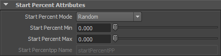
| Start Percent Mode |
This attribute allows a choice of two Start Percent modes :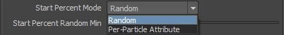 Start Percent mode of a Locomotion Behavior
|
| Start Percent Random Min |
See Random option of the Start Percent Mode above Available only when the Start Percent Mode is set to "Random" |
| Start Percent Random Max |
See Random option of the Start Percent Mode above Available only when the Start Percent Mode is set to "Random" |
| Start Percentpp Name |
Name of the float per-particle field of the relative particle system, containing the Start Percent value which will be used on the Motion (for more explanation about how to use ppAttributes, see ppAttributes Handling) |
Priority/Weight Attributes
If several Motion or Locomotion behaviors are played at the same time on the same part of the body, only the behaviors with the highest priority will be played. If several behaviors share the same priority, they will be blended together according to their weight normalized value (for instance, if two Motion behaviors share the same priority with a weight value of 1, they will be blended each at 50%).
See the Body Mask attribute to know how to apply a behavior on specific parts of the body
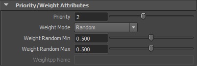
| Priority |
Priority to affect to Locomotion Behavior |
| Weight Mode |
This attribute allows a choice of two Weight modes :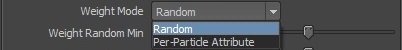 Weight mode of a Locomotion Behavior
|
| Weight Random Min |
See Random option of the Weight Mode above Available only when the Weight Mode is set to "Random" |
| Weight Random Max |
See Random option of the Weight Mode above Available only when the Weight Mode is set to "Random" |
| Weightpp Name |
Name of the float per-particle field of the relative particle system, containing the Weight value which will be used on the Motion (for more explanation about how to use ppAttributes, see ppAttributes Handling) Weight value is set to 0.5 if the ppAttribute name is empty or invalid Available only when the Weight Mode is set to "Per-Particle Attribute" |
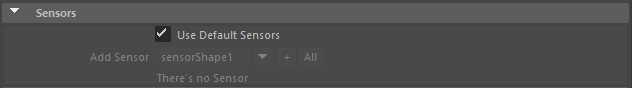
Sensors
This layout shows the Sensors that are used within the navigation behavior.
Navigation Behavior Sensors attributes
| Use Default Sensors |
When checked, the navigation behavior uses default sensors. The default sensors are:
|
| Sensors list | When Use Default Sensors is disabled, this control shows all the sensors that the navigation behavior uses (mapped to the CrowdBeNavigation node). Use the "+" and "-" buttons to add or remove sensors among the Sensor Locators in the scene. Without any mapped sensors, the navigation behavior will not be able to avoid entities or obstacles. |
Navigation And Locomotion Attributes
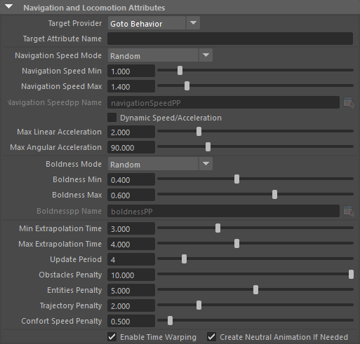
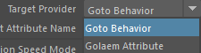
| Target Provider |
|
| Target Attribute Name |
When the target provider is a Golaem Attribute, here is the name of the Golaem Attribute that will be used as a target position |
| Navigation Speed Mode |
This attribute allows to choose how the navigation speed of each crowd entity is set:
The Navigation Speed value is in Crowd units. |
| Navigation Speed Min | See the Random option of the Navigation Speed Mode described above. Available only when the Navigation Speed Mode is set to Random. |
| Navigation Speed Max |
See the Random option of the Navigation Speed Mode described above. Available only when the Navigation Speed Mode is set to Random. |
| Navigation Speedpp Name |
Name of the float per-particle attribute containing the Navigation Speed value to use. For more explanations about how to use ppAttributes, see ppAttributes Handling. The Navigation Speed is set to 1 if the pp attribute name is empty or invalid. Available only when the Navigation Speed Mode is set to Per-Particle Attribute. |
| Dynamic Speed/Acceleration | When enabled, the Navigation Speed and Acceleration will be reread and changed dynamically while the behavior is running. |
| Max Linear Acceleration | Determines the max change of linear velocity when new velocities are computed. Higher value will allow a better reactivity but with the risk of glitches in the animation (unit: meters/second²). |
| Max Angular Acceleration | Cap the acceleration that can be produced by the blending to avoid too abrupt changes in chosen animations. In case the Delaunay triangulation, produced by locomotion database, has some very flat triangles, this may help having some fluid blending. Note that the preferred solution would be to have a coherent locomotion animation set that does not produce flat triangles. |
| Boldness Mode |
The boldness attribute of an entity controls how much an entity takes his neighbors into account in the navigation algorithm. The greater the boldness the less the entity will try to avoid its neighbors, simulating a "bold" behavior. This attribute allows to choose how the boldness of each crowd entity is set:
The Boldness value is between 0 and 1. |
| Boldness Min | See the Random option of the Boldness Mode described above. Available only when the Boldness Mode is set to Random. |
| Boldness Max | See the Random option of the Boldness Mode described above. Available only when the Boldness Mode is set to Random. |
| Boldnesspp Name |
Name of the float per-particle attribute containing the Boldness value to use. For more explanations about how to use ppAttributes, see ppAttributes Handling. The Boldness is set to 0.5 if the pp attribute name is empty or invalid. Available only when the Boldness Mode is set to Per-Particle Attribute. |
| Min Extrapolation Time, Max Extrapolation Time |
Time interval in which the entity predicts other entities/obstacles trajectories to calculate the path to avoid it. A low value of 1 sec for min and max, means the entity predicts the position of others 1 sec ahead. The actual extrapolation time is computed as a weighted average between the two parameters, using the boldness as weight (i.e. Extrapolation Time = Boldness * Min Extrapolation Time + (1 - Boldness) * Max Extrapolation Time ). |
| Update Period | Frequency at which new trajectories are extrapolated and evaluated (in frames) |
| Obstacles Penalty |
The multiplier used to combine the distance to obstacles penalty with other penalties More details in the Trajectory selection part of the algorithm. |
| Entities Penalty |
The multiplier used to combine the distance to entities penalty with other penalties More details in the Trajectory selection part of the algorithm. |
| Trajectory Penalty |
The multiplier used to combine the distance to desired trajectory penalty with other penalties More details in the Trajectory selection part of the algorithm. |
| Comfort Speed Penalty |
The multiplier used to combine the difference to the comfort speed penalty with other penalties More details in the Trajectory selection part of the algorithm. |
| Enable Time Warping |
If checked, the motion will be blended with time warping on limbs. Time warping is a technique that allows to locally change the speed ratio of a motion to ensure better synchronization with other motions. |
| Create Neutral Animation If Needed | If checked, an empty animation will be added in the Motion Clips set to ensure there is a motion for null linear and angular velocities. |
Trajectory Sampling Attributes
Note that the impact of each of theses parameters is better explained in the Trajectory selection part of the algorithm.
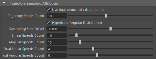
| Use Dual Command Extrapolation |
If checked, two commands will be used for each extrapolated trajectory. This option allows entities to better anticipate hard turns or angular changes, but at an heavy computation cost. |
| Trajectory Points Count |
Number of points in the trajectory extrapolation. |
| Hyperbolic Angular Distribution | An hyperbolic angular distribution gives more evenly sampled trajectories |
| Sampling Side Offset | Angular offset added to the angular speed distribution. A value of means as much trajectories extrapolated on left and right, while a non-null values means more trajectories extrapolated on one side than the other, and therefore more chances to avoid obstacles from this side rather than the other. |
| Linear Speeds Count | Number of different linear speeds to use for extrapolating trajectories |
| Angular Speeds Count | Number of different angular speeds to use for extrapolating trajectories |
| Dual Linear Speeds Count | Number of different linear speeds to use for the second command when dual command extrapolation is used |
| Dual Angular Speeds Count | Number of different angular speeds to use for the second command when dual command extrapolation is used |
Advanced Attributes
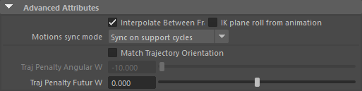
| Interpolate Between Frames |
If checked, the motions will interpolate postures between frames of the animation. This usually gives better results, but if your motions have a framerate superior or equal to the Maya framerate, this option can be unchecked for performances purposes. |
| IK plane roll from animation | This option should be checked when some specific animation produce a bad knee/elbow position on characters |
| Motions Sync mode |
This option specify how the animations in the locomotion set are synchronized together:
|
| Match Trajectory Orientation | Check this option to try to match the orientation towards the target while selecting trajectories. |
| Traj. Penalty Angular Weight |
Weight ratio between angular and linear distance when computing the trajectory penalty:
Note that linear distance and angular distance have different units: meter for linear distance and degrees for angular distance. Look at the Trajectory selection part of the algorithm for a more detailed explanation. |
| Traj. Penalty Futur Weight |
Weight ratio between points at the beginning and at the end of the trajectory when computing the trajectory penalty:
Look Trajectory selection part of the algorithm at the for a more detailed explanation. |
Visual Feedback Attributes
Defines the Locomotion Behavior Visual Feedback displayed in the Crowd Visual Feedback. For common Visual Feedback attributes see Behavior Common Attributes.
Notice that these attributes can also be configured in the Crowd Visual Feedback
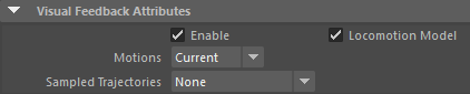
| Locomotion Model |
Show the locomotion model relative to the set of motions added to the Locomotion Behavior inside the Crowd Visual Feedback. 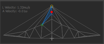
Locomotion Model in the Crowd Visual Feedback
The size of each dot is related to the Motion Clip current weight in the locomotion model.
A tooltip with the detail of the relative Motion Clip is available upon each intersections.
|
| Motions |
Show motions and their current weight inside the Crowd Visual Feedback according to the Motions mode:
|
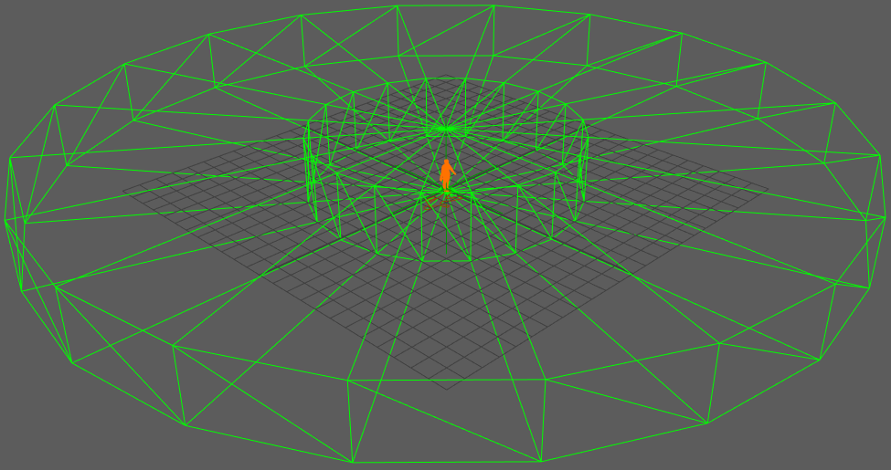
| Sampled Trajectories |
Display all trajectories that are computed from the current position/velocity and with the given set of motion and sample count.
|
Depending on the animation set, a one-dimension locomotion database might be detected as a two-dimension one, inducing some wrong blending between the motions at the extremity of the database. If such a thing occurs, the way to fix it is to increase the Delaunay Database Epsilon parameter located in the extra attributes of the Locomotion Behavior.
Algorithm
The Navigation and Locomotion Behavior works by predicting trajectories with different blending weights and computing penalties for each trajectory (depending on their distance to obstacles/entities, to their speed compared to the desired speed, the fact that it goes toward the target or not, ...). The behavior then simply select the trajectory that has the less penalty, and uses the blending weights it corresponds to drive the animation.
This process is repeated every few frames.
The complete algorithm consist in 3 main steps:
-
Trajectory sampling: a trajectory sampler computes a given number of possibles trajectories with the locomotion database;
-
Collision checks: a first selection occurs by dismissing trajectories that are in collision with the environment or the expected trajectory of other entities;
-
Trajectory selection: a penalty is computed for each remaining trajectory, and the linear/angular velocities for the trajectory with less penalty is chosen.
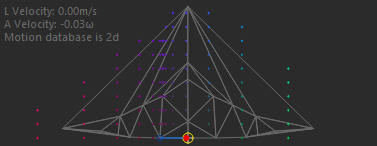
Step 1: Trajectory Sampling.
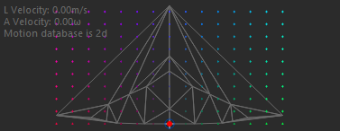
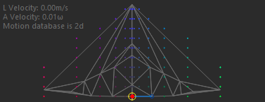
The trajectory sampling uses the Locomotion Database that is constructed by extracting the linear and angular velocities of each animation and adding them into a two-dimensional parametric space (one dimension being the linear velocity, the other dimension being the angular velocity), as represented in the following figure:
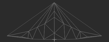
In this figure, connected dot represents a different Motion Clip with its linear velocity on ordinate (vertical axis) and its angular velocity on abscissa (horizontal axis). The dots are connected together to form triangles, and any linear/angular velocity inside these triangles can be reached by blending the 3 motions forming the triangle with different weights.
This parametric space is sampled with a given number of samples in linear velocity and angular velocity, and a trajectory is predicted for each sample.
For instance, when setting the parameters to 10 linear speeds count and 15 angular speeds count:

The parametric space will be sampled this way (each sample is represented by a colored dot):
Sampling of 10 linear and 15 angular speeds
Note that using an odd number for the count of angular speeds allows to have samples at null angular speed and evenly distributed on both sides.
But as some samples are out of any triangles formed by the animation velocities, they are filtered:
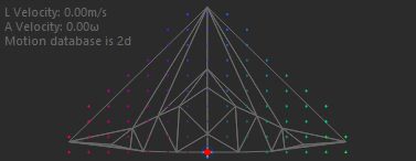
Sampling of 10 linear and 15 angular speeds, filtered to keep only valid samples
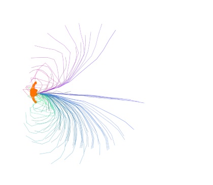
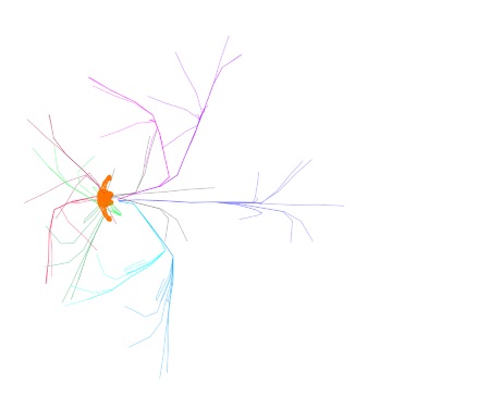
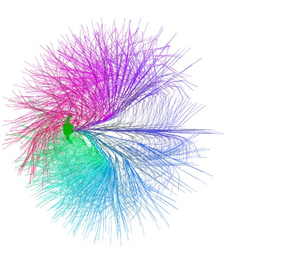
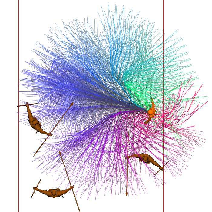
For each sample, a trajectory using the corresponding linear and angular velocities is computed:
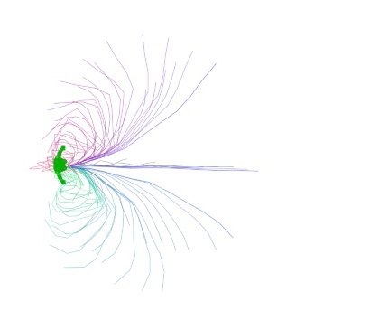
Trajectory prediction for each sample in the parametric space.
Note that the color of each trajectory is the same than it's corresponding sample in the parametric space. The color is computed this way:
- red on the left side
- green on the right side
- blue for higher linear velocities
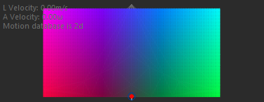
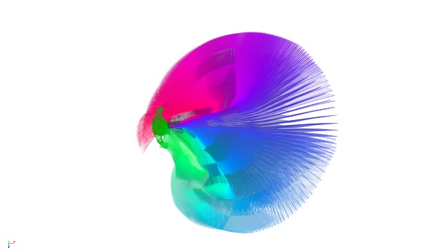
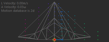
Color of the trajectories according to their linear and angular speed, as seen in the parametric space (up) and on the trajectory prediction (bottom).
Hyperbolic Distribution
Using evenly distributed angular speed samples do not result in evenly distributed trajectories (sides are more populated than the center). Using an hyperbolic distribution for angular speed allows more evenly distributed trajectories:
|
|
|
| Even distribution of angular speed result in unevenly distributed trajectories (left) while an hyperbolic distribution of angular speed result in more evenly distributed trajectories (right) | |
Sampling Side Offset
The sampling side offset value will be used to offset every angular sample. This will produce more samples on one side or the other, so might should allow to set an avoidance side preference.
|
|
|
|
| Negative side offset (right) | No side offset | Positive side offset (left) |


Dual Command
The dual command option allows to compute trajectories that use one sample of speeds values for their first half, and another for the second half. It help taking into account hard turns or hard stops.
 |
 |
| Example of dual command enabled (right) versus not disabled (left) with the same number of samples (2 linear and 5 angular) | |
But using the dual command option comes at a cost: it multiply the number of trajectories that need to be computed. For instance, if the Linear Speeds count is set to 10, and angular speed count to 15, it produces 10x15=150 different first half of trajectories to compute. If dual command is enabled, it produce 10x15=150 different second half trajectories for each first half, so 150x150=22500 different trajectories.
If each trajectory is 10 points, it's 225000 points to compute.
For a simulation of just 100 entities, that would already be up to 22 500 000 different points to compute every few frames.
It's far too much, that's why there are dedicated parameters for the second sampling (Dual Linear Speeds Count and Dual Angular Speeds Count)


Dual command parameters
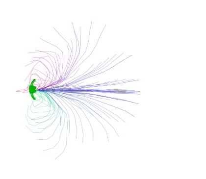
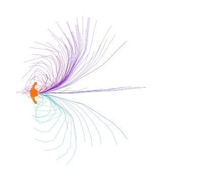
Trajectories predicted for the default count of linear/angular samples without (left) and with (right) dual command (without: less than 150 trajectories, with: up to 900 trajectories)
Step 2: Collision Checks
Collision checks simply get the list of perceived entities and obstacles (obtained from the sensors and perception) and check wether it collides with the predicted trajectories or not.
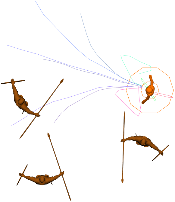 For each predicted trajectory |
Capsules are build along it |
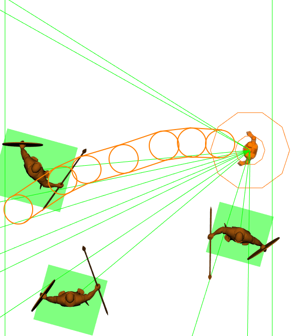 And collisions with entities or obstacles is computed |
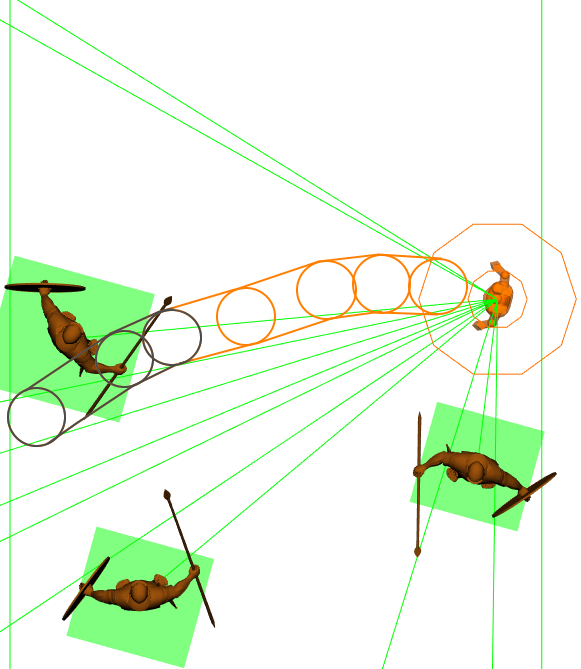 If there is collision, the trajectory is dismissed |
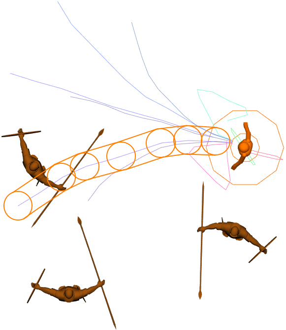
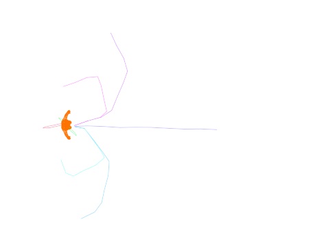
Any trajectory that collides with an entity or an obstacle is dismissed for the next part of the algorithm.
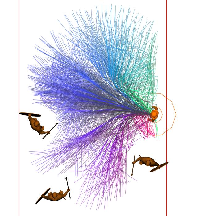
Example of the trajectories that were available before (left) and those left after (right) the collision checks
Step 3: Trajectory Selection.
Once trajectories are sampled, and colliding ones are filtered out, all other trajectories remain available, and a choice has to be done. The selection rely on penalties: different penalties will be computed for each trajectory, based on several criteria, and the trajectory with the lowest penalty will then be selected.
The different criteria are:
- the distance to the desired trajectory
- the distance to the comfort speed
- the distance to entities
- the distance to obstacles
For each of these criteria, a penalty between 0 and 1 is computed, and the final penalty is assembled by using the penalty weights given in parameter:
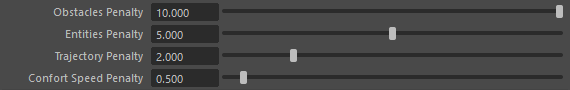
Penalty assemblage weights parameters
The final penalty is:
Penalty = Obstacles Penalty Parameter * Distance To Obstacle Penalty
+ Entities Penalty Parameter * Distance To Entities Penalty
+ Trajectory Penalty Parameter * Distance To Trajectory Penalty
+ Comfort Speed Penalty Parameter * Distance To Comfort Speed Penalty
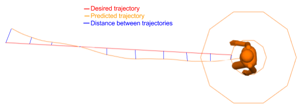
Distance to Trajectory Penalty
The distance to trajectory is the distance between the desired trajectory and the predicted trajectory for a given set of parameters. The distance is computed for each point of the trajectory, and summed together to obtain the full distance penalty.

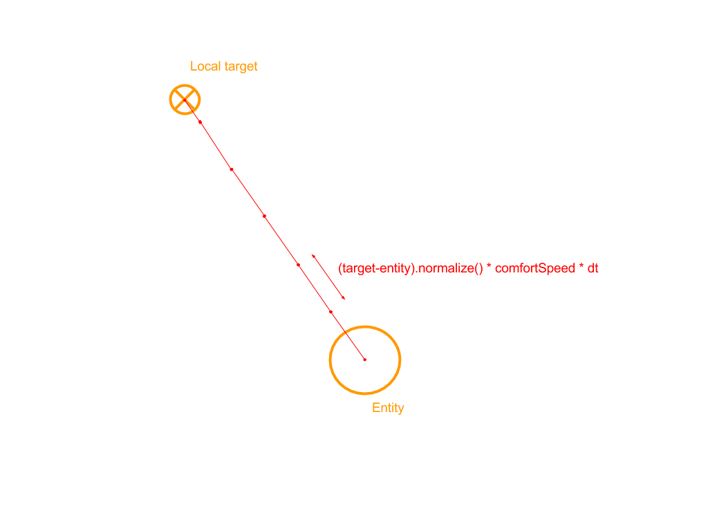
Desired Trajectory.
The desired trajectory is defined has the trajectory that point toward the current target at the comfort speed.
Linear Distance
The linear distance is the sum of Euclidean distance between each point of the desired trajectory and the equivalent point on the predicted trajectory.
Angular Distance

The angular distance is the sum of the angular difference between each point of the desired trajectory and the equivalent point on the predicted trajectory.
This computation is optional. If not used, any pelvis orientation will have the same chance of being selected, while when used, it will allow to prefer pelvis orientations that points toward the target rather than other orientations.
Future Weight

This changes the relative weight of distance computation for each point in the trajectory.
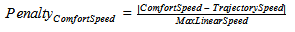
Distance to Comfort Speed Penalty
The distance to comfort speed penalty represents how the difference between the comfort speed and the predicted trajectory's speed.
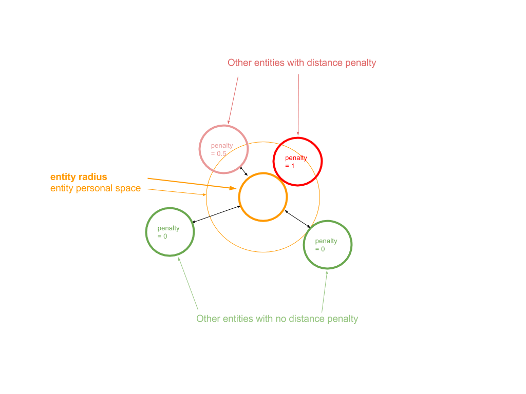
Distance to Entities Penalty
The distance to entity penalty is computed such that it is 0 when the distance with any other entity is further away than the entity's personal space, and 1 when the entity touch another one.

Distance to Obstacles Penalty
The distance to obstacle penalty is computed in a similar way: it is 0 when the distance with any obstacle is further away than the entity's personal space, and 1 when the entity touch the obstacle.
