


ChOp Sensor Input
The Channel Operator Sensor Input allows to input float values that depend on Sensors Locators into the graph of Channel Operators (ChOps).
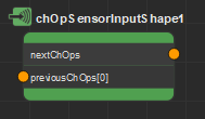
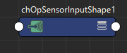
A Channel Operator Sensor Input seen in the Channel Operator Editor (left) and in the Maya Node Editor (right)
Creation
- From the Golaem Channel Operator Editor Tab key:
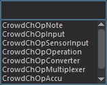
- From another Channel Operator:

- MEL command: addCrowdChOpSensorInput;
Configuration
The Channel Operator Sensor Input defines the following specific attributes. For common attributes, see Channel Operator Common Attributes.
Channel Operator Attributes
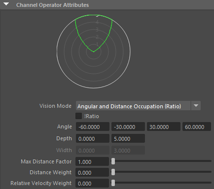
| Vision mode |
Defines what will be extracted from the Sensor Locators. Available values are:
|
| !Ratio | In Angular Occupation / Distance Occupation / Angular and Distance Occupation / Spherical Occupation modes, this option will change the output value to 1-(occupied ratio), which means it will be 1 when the vision is empty, and 0 when it's full rather than the opposite |
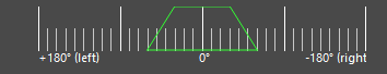
| Angle |
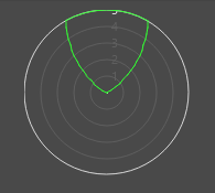
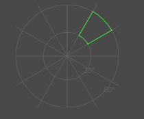
These parameters configure the zone in which checking for obstacle in the vision (represented as green zones in the Visual Feedbacks).
|
| Depth | |
| Width | |
| Max Distance Factor | Factor which will be multiplied by the greatest Depth or Width value to define the maximum distance at which computing the vision |
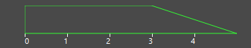
| Distance Weight | Allows the vision pixels to have a value between 0 and 1 according to the distance to the perceived obstacle - entities that are farther away are less taken into account, as in the figure below - w is the distance weight, alpha (α) is the pixel value, Dmin and Dmax are the values in the Depth paramete. 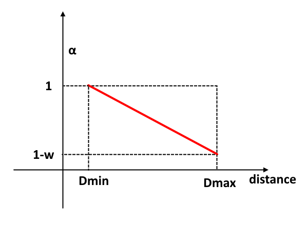 The Distance Weight is between 0 and 1. At 0 the distance is not taken into account and the pixels have the same alpha. |
| Relative Velocity Weight | This weight takes into account the velocity of the perceived object relative to the entity. This is projected along the front axis. The relative velocity is negative when the objects are seen as coming towards the entity and positive if the objects are seen as going away from the entity. In the figure below, rV is the relative velocity, S is the sum of the speeds of the entity and the perceived object and w the Relative Velocity Weight. The more the perceived object goes the same way as the entity, the lower its pixel alpha value. This allows lower the importance of objects that go in the same direction or away from the entity because there is no need to avoid them. If the Relative Velocity Weight is 0 the relative velocity is not taken into account and the pixels have the same alpha. The weight can be greater than 1, for example at a value of 2 the alpha will be 0 when rV is 0, which means that when a perceived object goes the same way and at the same speed or faster than the entity it will be invisible (thus not avoided).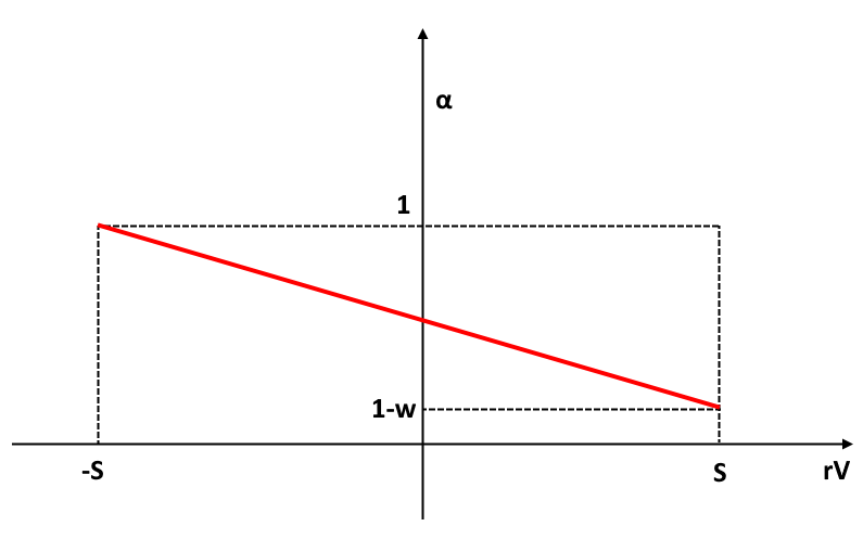 |
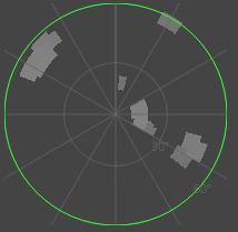

When changing any of those value, the display of the Sensor Input will be updated automatically.
Sensor Attributes
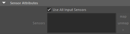
| Use All Input Sensors |
Check to use all the available input sensor (ie. currently started by an Activate Sensor Behavior) on the Entity |
| Sensors | If "Use All Input Sensors" is not checked, this list allows to determine which Sensor Locators to use. Note that any Sensor listed here should also be enabled using the Activate Sensor Behavior to be effectively used. |
Additional Inputs
These inputs are only taken into account in Maximum Clearance (Vector) and Minimum Clearance (Vector) modes.
| previous ChOps [0] | This input gives the world direction to choose when there are no obstacles. This allows the ChOps sensor input to use the local target of a Steer behavior for example, like going towards a poptool, a mesh or following a curve. |
| previous ChOps [1] | When there are obstacles, the clearance will actually be the closest point to the input direction within a tolerance to the absolute minimum (or maximum) alpha. This input gives this tolerance. The default value is 0.05. This allows to pick directions that are closer to the goal (given by the first input). |