


Asset Properties
As of August 5th, 2025, Golaem will no longer provide direct support.
All support for Autodesk Golaem will now be handled exclusively through Autodesk support channels and this website will be deactivated.
Please bookmark the Autodesk Golaem Support section for any future support needs related to Autodesk Golaem packages.
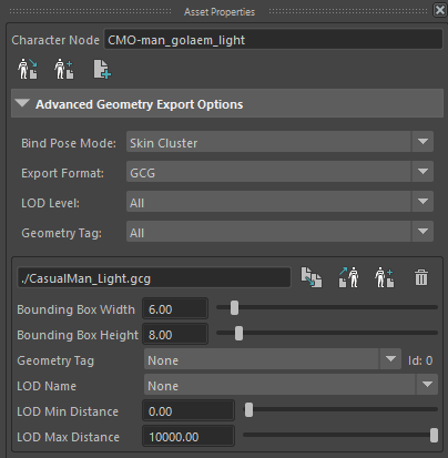
The Asset Properties panel displays all the properties of the selected Geometry Asset node and allows to edit these properties.
If the Asset Properties panel is hidden, right click on the Character Maker toolbar and check the Asset Properties.
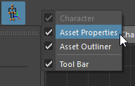
Display the Asset Properties panel
Character Node
Character Node properties
Name
To edit the name of the Character Node, edit the text box and press enter.
Geometry Files
The Character Node references all the Geometry Files of the Character (.fbx or .gcg files). Each of these files must contain the Character skeleton bones (the same skeleton which has been used to create the Skeleton part of the Character File), geometry and skinning to be used at render time (it can also optionally include blendshapes, geometry animation...). The Geometry file is used to store all available geometry for generating characters as well as the way they are skinned on the simulated skeleton.
In most cases, the Character node will contain only one Geometry File. But, if more control over the character's geometry is needed, such as LOD or secondary animation (flags, capes...), several Geometry Files can be provided and used in the Geometry Animation Behavior.
As the Character File only contains the name of the character meshes, it is important to make sure that the Geometry File (.fbx or .gcg) contains meshes with the EXACT names in it (including namespaces). Moreover, the geometry file has the same limitations as its format. i.e. when the geometry is stored in a FBX file, only features supported by the FBX file format are supported. The GCG file format is even more restrictive. For more information, see the rendering workflow.
Add a Geometry File
 Export Geometry File: exports all the meshes referenced in the Geometry Tab and the joint hierarchy matching the skeleton in the Skeleton Tab to a new fbx or gcg file. The file will be listed in the Asset Properties panel
 Append to the existing Geometry File: append non existing Mesh Assets in the existing Geometry file (existing meshes in the Geometry file are NOT replaced).
 Add Geometry File: adds an existing Geometry File. The fbx or gcg file will be listed in the Asset Properties panel
Advanced Geometry Export Options
BindPose Mode : it is best let as is. It is present for people having issues with the bindPose export, as Maya can store the skeleton bind pose in three locations : on the Skin Cluster, on a separate dagPose node (Bind Pose), or on the joints themselves (Current Values). Usually the three locations have matching data, but it can happen in some odd cases that the "good" bind pose is stored in only one of these locations.
Export Format : GCG by default is our custom geometry format, you might use FBX in very specific cases, but keep in mind that loading times are much longer with FBX (also at render time).
LOD Level : All by default, indicates the LOD levels to export in the file.
Geometry Tag : All by default, as for LOD, indicates the geometry tags to export in the file.
File Options
 Relocate Geometry File: change the path of an existing Geometry File by browsing a different FBX or GCG file
 Import Geometry File: imports the Geometry File in Maya
- Append to Geometry File: appends non existing Mesh Assets to the Geometry File (existing meshes in the Geometry file are NOT replaced).
 Remove Geometry File: removes the Geometry File from the Character
By default, Geometry File paths are set relative to the Golaem Character file, if the file exists (if the Golaem character was saved). To use absolute file paths, set the glmCrowdCharacterFileUseRelativePaths optionVar to 0.
Geometry File Bounding Box
Each Geometry File has a Bounding Box centered on the root bone defined in the Skeleton Tab. This bounding box is used by the renderers in order to check if it should call the Golaem Crowd procedural to render a character or not (see the rendering workflow). Bounding Box boundaries should be adapted to the character geometry and scale (taking into account the potential motions of the characters, e.g. if the character is a human and can raise its arms, a 1 meter margin should be added above the head).
The Bounding Box of a Character is computed automatically when its Geometry File is exported from the Character Maker but it's possible to adjust it manually by using the sliders in the Asset Properties panel under Width/Height. When the width and height are changed, the bounding box shape is displayed directly in the viewport, on the Character Maker Locator.
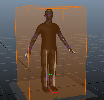
Character Maker Locator - Geometry File Bounding Box
Geometry Tag
Each Geometry File is tagged thanks to a Geometry Tag. A Geometry Tag allows to specify which Geometry File should be used in different steps of the Golaem workflow: during simulation, Cache Replay, render or geometry bake. Geometry File of a same Geometry Tag appear next to each other in the Character Node. The names of the available Geometry Tags can be customized using the glmGeometryTags optionVar.
LOD Name
As for Geometry Tag, indicates that this geometry file is to be used for the specific LOD level (or any by default)
LOD (Level of Detail) Min/Max Distance
Each geometry can be assigned a LOD min / max distance. If LOD is enabled when rendering, the geometry will be chosen according to object to camera distance. The geometry used will be the one which has the closest distance, among the available geometries of this tag, compared to the current camera distance. If several geometries are possible at a given distance, the first geometry found is used, thus it is better to avoid overlapping for LOD ranges. To export different levels of LOD, you must rename geometries to match the mesh asset nodes for the given LOD then export the geometry for that given LOD. Once configured here, LOD can be enabled for rendering on "Frustum Culling & LOD attributes" of Crowd Render Proxy. To enable LOD at previz, this is done on the Crowd Manager Simulation Render Attributes. Note that the camera distance is evaluated per entity, taking into consideration the entity scale (which can produce a gradient zone as below).
If the mesh is using a cloth, in rendering and previz alike, only the shortest distance LOD will display the cloth, others will use static (decimated) meshes.
Scene with LOD enabled for previz, using a single mesh asset, and two geometries : a sphere for distance 0 (LOD min)-100( LOD max), a cube for 100-15000. Using entity scales from 0.9 to 1.1 produce some progressive transition.
Asset Group Node
Asset Group Node properties
Name
To edit the name of the Asset Group Node, edit the text box and press enter. If an Asset Group Node with the same name already exists, a number will be added to the name, as it must be unique.
Asset Group Weights
To toggle the Asset Group as weighted or not, check or uncheck the Weighted checkbox. Only an Asset Group with two or more child nodes can be weighted. This property can also be changed in the Main Workspace. If an Asset Group is weighted, only one of its child nodes will be chosen at render time according to the Asset Group's weights, otherwise all of its child nodes will be chosen.
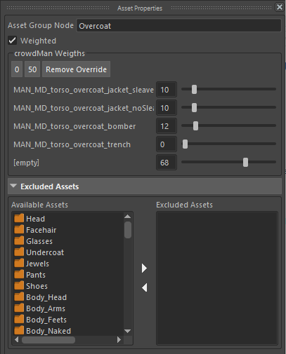
When the Asset Group is weighted, the weights of its child nodes are displayed. Weights can be adjusted using the sliders in the Asset Properties panel. Keep in mind that the displayed weights depend on the Rendering Type selected in the Rendering Types Panel. If no Rendering Type is selected (or the root "Rendering Types" item is selected), the weights displayed are the default weights. If a Rendering Type is selected, the weights displayed are the weights of the Asset Group in that Rendering Type. Weights can also be changed directly in the Rendering Types Panel with sliders, or in the Main Workspace.
To set all the weights to 0, click the "0" button above the weight sliders. No child node will be selected in this group. To set all the weights to 50, click the "50" button above the weight sliders. All the child nodes will have an equal chance to be selected at render time.
If the Asset Group overrides the default weights or the weights of a parent Rendering Type in a child Rendering Type, the Remove Override button is displayed. Pressing this button will restore the inherited weights of the Asset Group (default weights or weights from the parent Rendering Type).
To change the weights of the whole group to the same value, hold Shift while dragging the weight slider of one of the items in the group, or hold Shift and press Enter after having entered the weight value in the item's text box.
Excluded Assets
Because sometimes some meshes or fur assets are not compatible together, or because it will not be realistic for a character to have them together (e.g. shorts and a jacket), it is possible to create exclusion rules. These exclusion rules can be applied to either Asset Groups, Mesh Assets or Fur Assets. This means that if an Asset Group, Mesh Asset or Fur Asset is selected, the Character will not get any of its excluded assets, and vice versa.
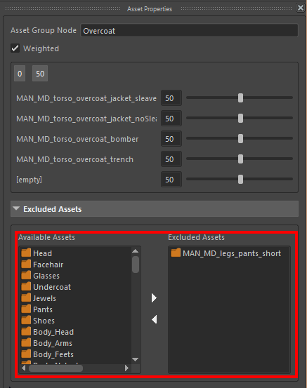
Example of Excluded Assets
In the example above, the overcoat and the shorts are mutually exclusive which means that at render time, if a character is generated with an overcoat, it will no be possible for it to get shorts. Because this is a mutual exclusion, it also means that if the character is generated with shorts, it will not be possible for it to get an overcoat.
To add one or more excluded assets, select them in the Available Assets list view and click the  button. The selected assets will be transferred to the Excluded Assets list view.
To remove one or more excluded assets, select them in the Excluded Assets list view and click the  button. The selected assets will be transferred back to the Available Assets list view.
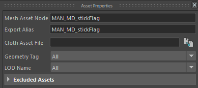
Mesh Asset Node
Mesh Asset Node properties
Name
To edit the name of the Mesh Asset Node, edit the text box and press enter. If a Mesh Asset Node with the same name already exists, a number will be added to the name, as it must be unique. Keep in mind that a Mesh Asset directly represents a mesh associated to the Character. Thus a mesh with this name must exist in the Character's geometry file.
Export Alias
The complete path to the asset when exported, with folders/transforms separated by a | character (maya style). The path must start with a | or be a single name (root export in that case), and must include the shape name. By default, when meshes are imported from maya, they will take the full path of the asset. This alias is used in alembic and USD exports.
Cloth Asset File
If you intend to use cloth simulation on a given mesh asset, this is where to specify the .apx cloth configuration file. See the Apex Cloth Behavior and the corresponding tutorial.
Notice: The .apx file should be generated from the Nvidia Maya DCC plugin for physX 3-3-4 (Windows only) (files from more recent version won't work)
By default, Cloth Asset File paths are set relative to the Golaem Character file, if the file exists (if the Golaem character was saved). To use absolute file paths, set the glmCrowdCharacterFileUseRelativePaths optionVar to 0.
Geometry Tag
If you intend to use this mesh in a specific Geometry Tag (previz, render, etc) you can mention it here, that information will be used at geometry file export time, to export only a given Geometry Tag.
This field can be prefilled when importing all geometry in the geometry tab, by using a string extra attribute on the maya mesh node, called "glmGeometryTag", and setting it to coma separated geometry tags (such as "previz, render")
LOD Level
As for Geometry Tag, if you intend to use this mesh in a specific LOD Level, you can mention it here, that information will be used at geometry file export time, to export only a given LOD Level.
This field can be prefilled when importing all geometry in the geometry tab, by using a string extra attribute on the maya mesh node, called "glmLodLevels", and setting it to coma separated LOD levels (such as "lod1, lod2")
Excluded Assets
See the detailed description above.
To add one or more excluded assets, select them in the Available Assets list view and click the button. The selected assets will be transferred to the Excluded Assets list view.
To remove one or more excluded assets, select them in the Excluded Assets list view and click the button. The selected assets will be transferred back to the Available Assets list view.
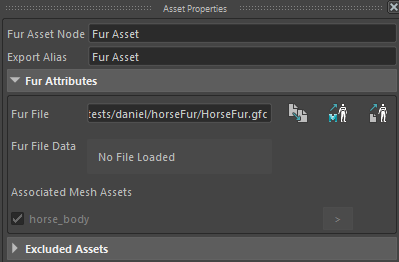
Fur Asset Node
Fur Asset Node properties
Name
To edit the name of the Fur Asset Node, edit the text box and press enter. If a Fur Asset Node with the same name already exists, a number will be added to the name, as it must be unique.
Export Alias
The complete path to the asset when exported, with folders/transforms separated by a | character (maya style). The path must start with a | or be a single name (root export in that case), and must include the shape name. By default, when meshes are imported from maya, they will take the full path of the asset. This alias is used in alembic and USD exports.
Fur Attributes
Attributes specific to Fur Assets are listed in this section.
Fur File
The Golaem Fur Cache file (.gfc) containing the fur description. If the file is not found, no fur will be rendered. Click on the  button to browse for a .gfc file, or on the Import Fur from Maya Curves
  or Import Fur from Alembic
  buttons to import fur from Maya Curves or Alembic file, and convert it to a .gfc file. For more details, see the Procedural Fur tutorial.
By default, Fur File paths are set relative to the Golaem Character file, if the file exists (if the Golaem character was saved). To use absolute file paths, set the glmCrowdCharacterFileUseRelativePaths optionVar to 0.
Fur File Data
Displays some information about the loaded file data, if any. If the file is a valid Golaem fur cache, it will display curve groups, curves, vertices, UVs, widths and skinning vertices count.
Associated Mesh Assets
This lists the Mesh Assets on which the current Fur Asset is attached / has been groomed. If a Mesh Asset is unchecked here, the fur will not be generated on this mesh. If a mesh asset is grayed out, it's not present in the Golaem character file and the fur will be generated on this mesh. To select the associated Mesh Asset, click on the Select mesh node ">" button.
If the Mesh Assets used for the fur need to be invisible at render time on the Character, its Asset Visibility attribute can be overriden.
Excluded Assets
See the detailed description above.
To add one or more excluded assets, select them in the Available Assets list view and click the button. The selected assets will be transferred to the Excluded Assets list view.
To remove one or more excluded assets, select them in the Excluded Assets list view and click the button. The selected assets will be transferred back to the Available Assets list view.
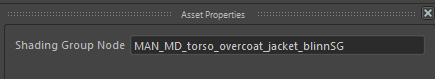
Shading Group Node
Shading Group Node properties
Name
To edit the name of the Shading Group Node, edit the text box and press enter. If a Shading Group Node with the same name already exists, a number will be added to the name, as it must be unique. Keep in mind that a Shading Group Node directly represents a shading group applied on a mesh of the rendered geometry or a fur asset. The Maya scene being rendered must contain the shading group with the same name at render time, otherwise the meshes or fur assets using the Shading Group Node will be rendered with the default shader (for more info, see the rendering workflow).
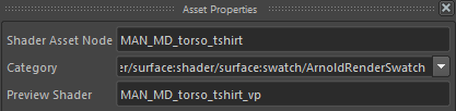
Shader Asset Node
Shader Asset Node properties
Name
To edit the name of the Shader Asset Node, edit the text box and press enter. If a Shader Asset Node with the same name already exists, a number will be added to the name, as it must be unique. Keep in mind that a Shader Asset Node directly represents a shader applied on a mesh of the rendered geometry or a fur asset. The Maya scene being rendered must contain the shader with the same name at render time, otherwise the meshes or fur assets using the Shader Asset Node will be rendered with the default shader (for more info, see the rendering workflow).
Category
The category of the shader determines the type of the shader for Golaem. When importing a shader from Maya, the category is filled automatically. Three types of shaders are supported:
 Surface shaders: these shaders can be handled by all renderer plugins. A surface shader corresponds to the surface material attached to a Maya shading group. A Shader Asset is considered a surface shader if its category contains the keyword surface.
 Displacement shaders: these define how the geometry of the character is displaced at render time. A Shader is considered a displacement shader if its category contains the keyword displace.
 Contour shaders: these define how the contours of characters are drawn at render time. A Shader is considered a contour shader if its category contains the keyword contour.
The category can be changed using the Category combo box, either by choosing a predefined one, or by typing it directly into the checkbox. If the category is unsupported, the Shader Asset will be displayed with the icon  the Main Workspace.
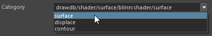
Shader Asset Node Category
Preview Shader
The Preview Shader indicates the name of the shader to use only in the Maya viewport for previsualisation. The Preview Shader allows to use a simpler shading network for previz if the rendering shaders are too complex. If the Preview Shader is not present in the scene, the Shader Asset name will be used instead.
Shader Attribute Node
Name
To edit the name of the Shader Attribute Node, edit the text box and press enter. If a Shader Attribute Node with the same name already exists, a number will be added to the name, as it must be unique. Keep in mind that a Shader Attribute Node is usually a parameter in a user data shader (see Simulation Render), thus it must have a match in the Maya scene at render time.
Type
The type of a Shader Attribute can be edited using the Type combo box. There are 4 possible types of Shader Attributes:
- int: the value of the shader attribute is an integer
- float: the value of the shader attribute is a float
- vector: the value of the shader attribute is a vector (3 floats)
- string: the value of the shader attribute is a string
The other properties of the Shader Attribute change according to its type.
Integer Shader Attribute Properties
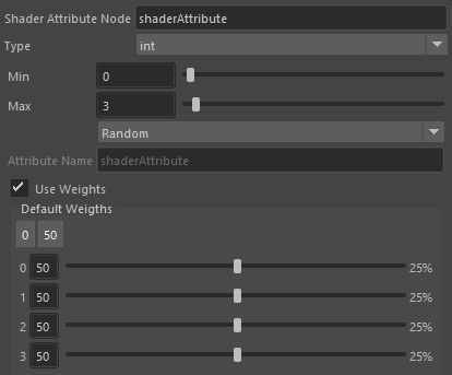
| Min | The minimum integer value of the Shader Attribute. This is only available when the Mode is set to Random, which means that the value is randomly drawn between the Min and the Max values. |
| Max | The maximum integer value of the Shader Attribute. This is only available when the Mode is set to Random, which means that the value is randomly drawn between the Min and the Max values. |
| Mode | Specify if the value is random, read from the Golaem or PP attribute given by Attribute Name or fed by a Channel given by the name of the Shader Attribute. Available Channels are : entityIdx, entityId, characterIdx, renderingTypeIdx and geometryFileIdx |
| Attribute Name | The name of the Golaem or PP attribute from which to read the value of the Shader Attribute. This is only available when the Mode is set to Attribute. |
| Use Weights | When checked, integer values are picked according to their weight. This is only available when the Mode is set to Random. The weight values depend on the Rendering Type selected in the Rendering Types Panel. If no Rendering Type is selected (or the root "Rendering Types" item is selected), the weights displayed are the default weights. If a Rendering Type is selected, the weights displayed are the weights of the Shader Asset in that Rendering Type. Weights can also be changed directly in the Rendering Types Panel with sliders. |
To change the weights of the whole group to the same value, hold Shift while dragging the weight slider of one of the items in the group, or hold Shift and press Enter after having entered the weight value in the item's text box.
Float Shader Attribute Properties
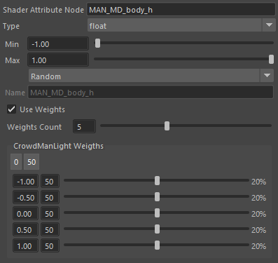
| Min | The minimum float value of the Shader Attribute. This is only available when the Mode is set to Random, which means that the value is randomly drawn between the Min and the Max values. |
| Max | The maximum float value of the Shader Attribute. This is only available when the Mode is set to Random, which means that the value is randomly drawn between the Min and the Max values. |
| Mode | Specify if the value is random, read from the PP attribute given by PP Name. |
| Attribute Name | The name of the Golaem or PP attribute from which to read the value of the Shader Attribute. This is only available when the Mode is set to Attribute. |
| Use Weights | When checked, float values are picked according to their weight. This is only available when the Mode is set to Random. The weight values depend on the Rendering Type selected in the Rendering Types Panel. If no Rendering Type is selected (or the root "Rendering Types" item is selected), the weights displayed are the default weights. If a Rendering Type is selected, the weights displayed are the weights of the Shader Asset in that Rendering Type. Weights can also be changed directly in the Rendering Types Panel with sliders. |
| Weights Count | The number of weights when Use Weights us checked. The minimum is 2 values, which are the Min and the Max. |
Each float value, except the first and the last (which are locked to the Min and Max values), can be edited by selecting its text box. The values are reordered if needed once they are validated. Any value can be drawn between the Min and the Max value, with a probability which is interpolated between the weight just above and the one just below it.
To change the weights of the whole group to the same value, hold Shift while dragging the weight slider of one of the items in the group, or hold Shift and press Enter after having entered the weight value in the item's text box.
Vector Shader Attribute Properties
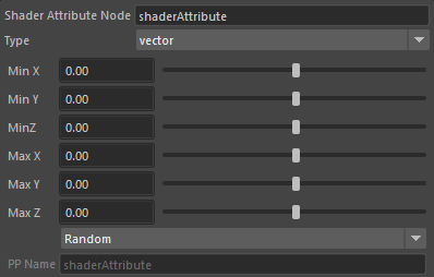
| Min X/Y/Z | The minimum vector value of the Shader Attribute. This is only available when the Mode is set to Random, which means that the value is randomly drawn between the Min and the Max values. |
| Max X/Y/Z | The maximum vector value of the Shader Attribute. This is only available when the Mode is set to Random, which means that the value is randomly drawn between the Min and the Max values. |
| Mode | Specify if the value is random, read from the PP attribute given by PP Name. |
| Attribute Name | The name of the Golaem or PP attribute from which to read the value of the Shader Attribute. This is only available when the Mode is set to Attribute. |
When using attributes to feed Shader Attributes, keep in mind that the Golaem or PP attributes must be exported in the Simulation Cache.
Skeleton Override Node
Allows to define per-bone scales, as shown here with the normal size shown in green (let side), and a mix of normal/tall/short characters in blue.
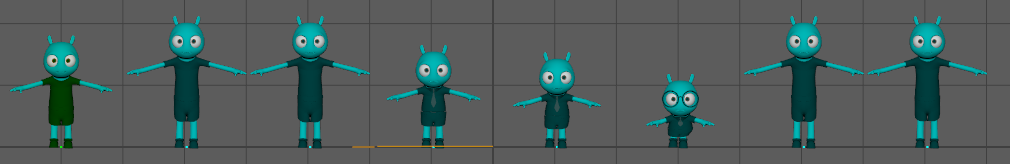
A character with skeleton override nodes
Name
To edit the name of the Skeleton Override Node, edit the text box and press enter. If a node with the same name already exists, a number will be added to the name, as it must be unique.
Bones Positions Scales
Bone positions scales allows to define longer / shorter bone sizes
Bones Orientations Offsets
Bone orientation offsets allows to define an orientation offset for each bone. The orientation offset will be applied on the entity after everything else is performed (behavior, physics, ...)
Skinning Scales
The skinning scales allows to add some scale on the skinning matrix for a bone. This scale will be reflected on the mesh that is applied on the bone, allowing to make some squash&stretch effect, or simply making sure that the bone position scale also looks correct on the mesh.
Weights ranges and Random Seed
Each set of parameters (positions scales, orientations offsets and skinning scales) have weights ranges that allows to set diversity for entities:
- if set to (1:1), then all entities will have the same set of values
- if set to (0:0), then all entities will have a neutral set of values (same effect than if the Skeleton Override Node is let to it's default values)
- if set to (0:1), entities will have different values, ranging from the default value to the value defined for each bone.
The random seed is used to change the distribution of weight for each entity. If entities needs to use the same weight for several Skeleton/Blind Data Overrides Nodes, then they simply need to use the same Random Seed.
The weight range allows to define a whole range of variations with a single definition. Here is for instance a weight range of 0 - 2 on a single 'tall character' skeleton override node:
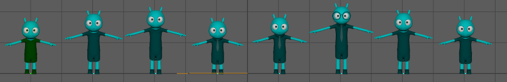
Using the weight range to bring more size diversity without writing each individual value
Blind Data Override Node
Name
To edit the name of the Blind Data Override Node, edit the text box and press enter. If a node with the same name already exists, a number will be added to the name, as it must be unique.
Blind Data Values
When the character defines blind data, this panel allows to set their values.
Weights ranges and Random Seed
Blind data values have weights ranges that allows to set diversity for entities:
- if set to (1:1), then all entities will have the same set of values
- if set to (0:0), then all entities will have a neutral set of values (same effect than if the Blind Data Override Node is let to it's default values)
- if set to (0:1), entities will have different values, ranging from the default value to the value defined for each bone.
The random seed is used to change the distribution of weight for each entity. If entities needs to use the same weight for several Skeleton/Blind Data Overrides Nodes, then they simply need to use the same Random Seed.
Physics Override Node
Adding a physics override node will replace the Physics properties of a given bone. The only property that can't be overriden is the fact that the bone is enabled for physics or not.
Bone
The bone for which physics properties have to be override.
All other properties are the same than these explained in the Physics Properties Dialog.